TM-9-2520-272-40 - Page 481 of 620
TM 9-2520-272-40
0059
SUSTAINMENT MAINTENANCE
REPAIR BEVEL GEAR ASSEMBLY
INITIAL SETUP:
Tools and Special Tools
Adapter, Socket Wrench Drive, 3/8” Male x 1/2”
Female (WP 0079, Item 2)
Crowfoot Attachment, Flare Nut, 3/8” Drive, 9/16”
(WP 0079, Item 11)
Extension, 3/8” Drive, 6” (WP 0079, Item 16)
Hammer, Hand, Soft-Face, Dead Blow, 52 oz
(WP 0079, Item 19)
Pliers Set, Retaining Ring (WP 0079, Item 27)
Press, Arbor, Hand, 25 Ton (WP 0079, Item 28)
Socket Wrench, Universal, 3/8” Drive, 6-Point, 9/16”
(WP 0079, Item 39)
Tool Kit, General Mechanic’s (GMTK) (WP 0079,
Item 45)
Materials/Parts
Block, Wood, Lumber, Soft Wood (WP 0078, Item 3)
(2 - 16 in. lengths)
Nut, Self-Locking, Hex (WP 0080, Item 24)
O-Ring (WP 0080, Item 42) (2)
Packing, Preformed (WP 0080, Item 40)
Petrolatum, Technical (Petroleum Jelly) (WP 0078,
Item 12)
Rag, Wiping (WP 0078, Item 13)
Seal Ring, Metal (WP 0080, Item 14) (2)
Personnel Required
Track Vehicle Repairer, 91H10
Equipment Condition
Transmission removed from vehicle or container (TM
9-2350-277-13&P)
Oil f ll tube assembly removed (WP 0006)
Input housing assembly removed (WP 0042)
NOTE
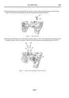
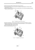
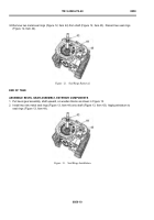
The bevel gear assembly does not have to be removed from the transmission to remove
exterior components. However, text and illustrations in this work package are based upon the
bevel gear assembly removed from the transmission.
0059
‐
1
Back to Top

