TM-9-2520-272-40 - Page 482 of 620
TM 9-2520-272-40
0059
DISASSEMBLE BEVEL GEAR ASSEMBLY, EXTERIOR COMPONENTS
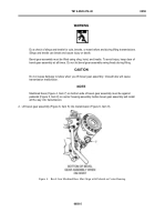
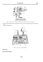
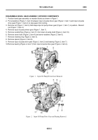
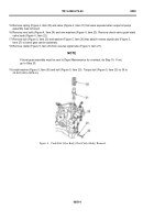
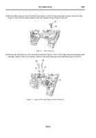
1. Position bevel gear assembly on wooden blocks as shown in Figure 1.
2. Put screwdriver (Figure 1, Item 3) between input oil pump driven gear (Figure 1, Item 1) and input oil pump
drive gear (Figure 1, Item 2) to stop gears from turning.
3. Remove nut (Figure 1, Item 4) that keeps input oil pump driven gear (Figure 1, Item 1) in position. Discard
nut (Figure 1, Item 4).
4. Remove input oil pump driven gear (Figure 1, Item 1).
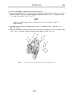
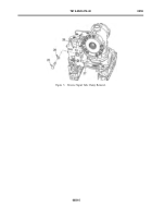
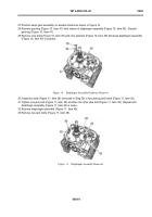
5. Remove woodruff key (Figure 2, Item 11) from input oil pump shaft (Figure 2, Item 10).
6. Remove seven bolts (Figure 2, Item 8) and seven washers (Figure 2, Item 9).
7. Remove retaining ring (Figure 2, Item 5).
8. Remove spacer (Figure 2, Item 6).
9. Remove input oil pump drive gear (Figure 2, Item 2) and bearing (Figure 2, Item 7).
10.Remove bearing (Figure 2, Item 7) from input oil pump drive gear (Figure 2, Item 2).
Back to Top

