TM-9-2815-200-35
ENGINE, WITH CONTAINER:TURBOSUPERCHARGED, DIESEL ,FUEL INJECTION ,90-DEGREE “V” TYPE, AIR - COOLED ,12 - CYLINDER , ASSEMBLY ;MODELS AVDS-1790-2M (2815-856-4996), AVDS-1790-2A AND AVDS-1790-2AM (2815-856-9005)
TECHNICAL MANUAL; DIRECT SUPPORT, GENERAL SUPPORT AND DEPOT MAINTENANCE MANUAL INCLUDING REPAIR PARTS AND SPECIAL TOOLS LISTS
TM-9-2815-200-35 - Page 335 of 779
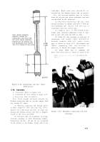
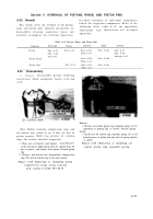
NOTE. BEFORE REAMING,
LUBRICATE THREADS ON
CONNECTING ROD BOLTS AND
NUTS WITH THREAD LUBRICANT,
(OR EQUIVALENT) AND TIGHTEN
NUTS TO A TORQUE OF 950 LB-INS.
crankshaft. Right bank rods (marked R) ar e
installed on the damper flange side of journal .
Note.
All location numbers must be visabl e
from the oil pan side when crankshaft and rod s
are installed in the crankcase .
(3) Position connecting rod cap, wit h
bearing installed, on journal and mate it with the
corresponding rod .
Secure rod and cap t o
crankshaft with two slotted nuts .
(4) Tighten nut s
to 950 pound-inche s
torque, plus sufficient additional torque to aline
slots in nuts with cotter pin holes in bolts.
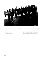
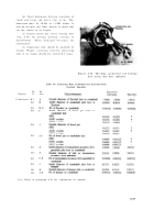
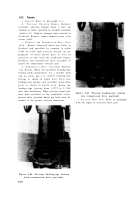
(5) Check the side clearance of each pair of
connectin g
rods against limits specified i n
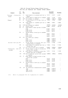
overhaul standards (table 6-9), using a feele r
gage as shown in figure 6-37. Disassemble and
replac e
connectin g
rod s
and bearings a s
necessary to obtain the proper clearance .
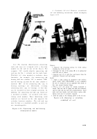
(6)
Secure
slotted
nuts
to
connecting
rod
bolts with cotter pins as shown in figure 6-30 .
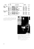
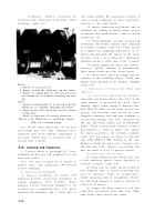
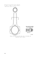
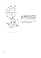
Figure 6-36. Connecting rod bore cente r
dimensions .
6-18. Assembly
a. Crankshaft.
Refer to figure 6-33 .
b. Crankshaft Oil Seal.
Refer to figure 6-32 .
c.
Connecting Rod Assemblies .
Note.
Total weight variation between in -
dividual connecting rods on any one engine shall
not exceed 0.5 ounce .
(1) Position connecting rod bearing halve s
in their respective rods and caps (fig. 6-31) .
Install two connecting rod bolts in each con -
necting rod making certain each bolt is properly
seated in the recess provided .
(2) Position rods on crankshaft in prope r
location according to their identifying number .
Connecting rod Nos. 1R and 1L are assembled
on the journal at the damper flange end of th e
Figure 6-37. Checking connecting rod sid e
clearance .
6-41
Back to Top


