TM-9-2815-200-35
ENGINE, WITH CONTAINER:TURBOSUPERCHARGED, DIESEL ,FUEL INJECTION ,90-DEGREE “V” TYPE, AIR - COOLED ,12 - CYLINDER , ASSEMBLY ;MODELS AVDS-1790-2M (2815-856-4996), AVDS-1790-2A AND AVDS-1790-2AM (2815-856-9005)
TECHNICAL MANUAL; DIRECT SUPPORT, GENERAL SUPPORT AND DEPOT MAINTENANCE MANUAL INCLUDING REPAIR PARTS AND SPECIAL TOOLS LISTS
TM-9-2815-200-35 - Page 331 of 779
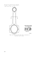
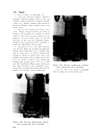
(d) Check dimension between centerline o f
small and large end bores (fig. 6-36). Thi s
dimension must be 10.998 to 11.002 inches. I f
rods do not meet this limit, destroy to insure rods
are not reused in an engine .
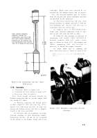
(e) Inspect piston pin sleeve bearing bore
(fig. 6-34) for pitting, galling, scoring, o r
discoloration .
Mark damaged bearings fo r
replacement .
(f) Connecting rods should be matched by
weight. Weight variations between connectin g
rods in an engine should not exceed 0.5 ounce .
Fig
Component
No.
Crankshaft B- 3
B-3
B-3
B-3
B-3
B-3
B-3
B-3
B-3
B-3
B-3
B-3
Ref.
letter
K
M
M-K
P
S
S-P
R
N
N-R
A
B
A-B
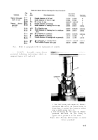
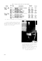
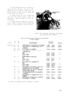
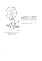
Figure 6-34. Checking connecting rod bearin g
bore using dial bore indicator .
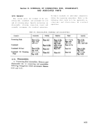
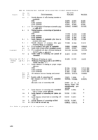
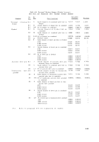
Table 6-9. Connecting Rods, Crankshaft and Associated Parts
Overhaul Standards
Note.
Refer to paragraph 6-3b for explanation of symbols.
6-37
Back to Top

