TM-9-2815-200-35
ENGINE, WITH CONTAINER:TURBOSUPERCHARGED, DIESEL ,FUEL INJECTION ,90-DEGREE “V” TYPE, AIR - COOLED ,12 - CYLINDER , ASSEMBLY ;MODELS AVDS-1790-2M (2815-856-4996), AVDS-1790-2A AND AVDS-1790-2AM (2815-856-9005)
TECHNICAL MANUAL; DIRECT SUPPORT, GENERAL SUPPORT AND DEPOT MAINTENANCE MANUAL INCLUDING REPAIR PARTS AND SPECIAL TOOLS LISTS
TM-9-2815-200-35 - Page 333 of 779
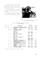
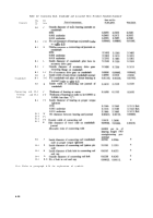
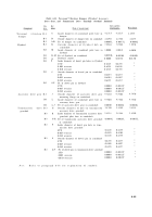
Table 6-9. Connecting Rods, Crankshaft and Associated Parts Overhaul Standards
-
Continued
Fig.
Ref.
Sizes and fits
Component
No.
letter
Point of measurement
of new parts
Wear limits
B-4
RR
Outside diameter of split sleeve bearing must
be press fit in bore. Burnish to seat sleeve
bearing prior to finish diameter
B-4
SS
Inside diameter of bushing-type sleeve bearing
2.0025
2.0027
2.0040
B-4
H
Outside diameter of piston pin
2.0000
2.0002
B-4
SS-H
Fit of pin in bearing
1.9998
0.0023L 0.0027L
0.0042L
Note.
Refer to paragraph 6-3b for explanation of symbols.
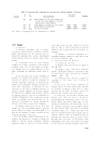
6-17. Repair
a. Crankshafts .
(1) Replace crankshafts that are deepl y
scratched, nicked, burred, scuffed or galled .
Minor imperfections in the journals may b e
repaired by polishing with a crocus cloth dipped
in dry-cleaning solvent or mineral spirits pain t
thinner .
(2) Crankshafts that are worn beyon d
standard wear limits specified in the overhau l
standards (table 6-9) or with journal or crank -
case damage may be ground undersize to th e
limits established for crankshaft rework (table 6-
9) .
(3) In the event any of the crankpins o r
journals are found unserviceable, it will b e
necessary to polish or grind all crankpins o r
journals uniformly undersize to maintain th e
balance of the crankshaft. Extreme care must be
taken when regrinding, to maintain the con -
centricity of the entire crankshaft and not t o
exceed a surface roughness of 12 micro inches .
All radii on the crankpins and journals, effected
by grinding undersize, must be re-established to
original configuration .
The crankshaft nitrid e
finish of crankpins and journals must be in -
spected by magnaflux or similar method fo r
fractures and surface cracks after finishing .
(4) Replace dowel pins (18 fig. B-3) an d
straight pins (25) in crankshaft flange if pins do
not fit securely in flange, are out-of-round or if
pins do not conform to limits specified in the
overhaul standards (table 6-9) .
Note.
The headless grooved dowel pins in th e
flywheel end flanges are available in 0.005 and
0.010 in. oversize. Ream crankshaft flywhee l
mounting flange to necessary oversize dimen -
sions and install new pins. Whenever oversiz e
pins are used, it will be necessary to ream the
flywheel and transmission drive gearshaft ac -
cordingly .
(5) Replace a cracked crankshaft or a
crankshaft showing evidence of wear due to bent
or twisted connecting rods .
b. Connecting Rods and Bearings .
(1) Connecting rod bolts .
(a) Replace bolts that do not fit snugly in
rod and cap .
(b) Replace bolt s
that have damage d
threads, galled pilot diameters, or diameters tha t
are not within limits specified in overhau l
standards
(table
6-9).
(c) Replace bolts that are cracked o r
scratched, o r
tha t
sho w
an y
evidence o f
stretching .
(2)
Connecting rod bearings.
Replace al l
bearings that do not check within limits specified
in overhaul standards (table 6-9) or whe n
bearings do not show 75 percent contact b y
Prussian blue transfer after bore check .
(3) Connecting rod assembly.
Discard con -
nectin g
rod s
that are bent or distorted .
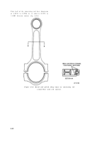
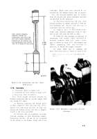
Straightening of connecting rods is not per -
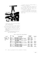
mitted. Break and polish sharp edges at con -
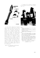
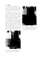
necting rod counterbore and rod contour (fig. 6 -
35). Replace connecting rod assemblies whic h
are not within limits specified in overhau l
standards (table 6-9). Connecting rods wit h
worn or damaged piston pin bearing may b e
repaired. Replace worn or damaged piston pi n
bushing-type bearing using an arbor press .
Bearing split line must be 90 degrees fro m
longitudinal center line. Line-ream new bearing
to size shown in overhaul standards (table 6-9) .
6-39
Back to Top

