TM-9-2815-200-35
ENGINE, WITH CONTAINER:TURBOSUPERCHARGED, DIESEL ,FUEL INJECTION ,90-DEGREE “V” TYPE, AIR - COOLED ,12 - CYLINDER , ASSEMBLY ;MODELS AVDS-1790-2M (2815-856-4996), AVDS-1790-2A AND AVDS-1790-2AM (2815-856-9005)
TECHNICAL MANUAL; DIRECT SUPPORT, GENERAL SUPPORT AND DEPOT MAINTENANCE MANUAL INCLUDING REPAIR PARTS AND SPECIAL TOOLS LISTS
TM-9-2815-200-35 - Page 524 of 779
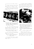
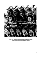
1. Cover 12 cylinder exhaust ports (A).
4. Cover oil filler and oil level indicator openings (D) and
2. Cover 12 fuel injector nozzle holder assembly ports (B).
cylinder head oil drain tube openings (E).
3. Cover starter adapter opening (C)
:
5. Cover oil cooler inlet and outlet hose openings (F) on
each side of crankcase damper and oil filter housing.
Figure 7-16. Protecting openings to prevent entrance of dust and
foreign objects .
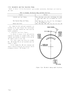
7-9.
Fan Drives, Housings, and Base s
assembly instructions. References are listed i n
Refer to Table 7-5 for illustrations an d
the table .
Table 7-5. Fan Drives, Housings, and Bases
Component
Reference
Rear Fan and Accessory Drive Housing with Clutch
Para 7-9a, Fig. 5-134, 5-133, 5-131, 7-17, 5-130, 5-129
Assembly and Mounting Base
Fuel Injection Pump Mounting Base
Para 7-9b, Fig. 5-128, 5-127
Front Fan Drive Housing with Clutch Assembly and
Para 7-9c, Fig. 5-126, 5-125, B-
, 7-18, 5-123, 5-122, 5-
Mounting Base
120 through 5-117, 7-19
a. Rear Fan and Accessory Drive Housin g
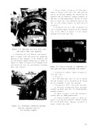
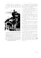
(2) Refer to figure 5-133 and torque tighten
with Clutch Assembly and Mounting Base .
screws and nuts to 275 pound-inches. Apply a
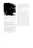
(1) Install three new preformed packings on
thin
coat
of
gasket
cement
(MIL-C-10523
Ord.)
oil transfer tubes in crankcas e
(fig. 5-134) .
on the mounting surface of the base prior t o
Apply a thin coat of gasket cement (MIL-C -
assembling rear fan and accessory drive housing.
10523 Ord) to mounting base lower mountin g
surface before assembly to crankcase .
7-12
Back to Top


