TM-9-2815-200-35
ENGINE, WITH CONTAINER:TURBOSUPERCHARGED, DIESEL ,FUEL INJECTION ,90-DEGREE “V” TYPE, AIR - COOLED ,12 - CYLINDER , ASSEMBLY ;MODELS AVDS-1790-2M (2815-856-4996), AVDS-1790-2A AND AVDS-1790-2AM (2815-856-9005)
TECHNICAL MANUAL; DIRECT SUPPORT, GENERAL SUPPORT AND DEPOT MAINTENANCE MANUAL INCLUDING REPAIR PARTS AND SPECIAL TOOLS LISTS
TM-9-2815-200-35 - Page 528 of 779
7-10. Camshafts and Fuel Injection Pum p
Refer to Table 7-6 for illustration s
and assembly instructions. References are listed i n
the table .
Table 7-6. Camshafts, Fuel Injection Pump, and Rocker Arm Covers
Component
References
Camshafts and Valve Timing
Para 7-10a, Figs. 5-116, 5-115, 7-20 through 7-22, 5-106,
5-109, 5-105, 5-108, 7-22, 7-23 through 7-26, 5-112, 5-
111
Fuel Injection Pump and Timing
Para 7-10b, Figs. 4-71, 4-72, 7-27, 7-28, 4-65 through 4-
68, 4-75 through 4-81, 7-29
Rocker Arm Covers
Para 7-10C, Figs. 5-109, 5-108, 7-22, 7-23, 7-27, 7-28, 7-30
Note.
Both the left and right camshafts ar e
installed in the same manner. For instructiona l
purposes, the right camshaft has been used fo r
typical procedures .
a .
Camshafts and Valve Timing .
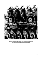
(1) Refer to figure 5-116 and positio n
camshaft on bearings in cylinder heads. Attach
camshaft gear housing to cylinder (5-115) but do
not tighten screws at this time .
Note.
Valve rocker arm covers for cylinde r
Nos. 2R through 5R are not installed until the
engine is timed .
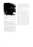
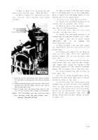
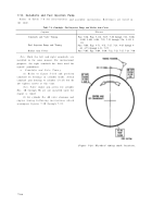
(2) Set cylinder No. 6R valve clearance and
engine timing following instructions whic h
accompany figures 7-20 through 7-22 .
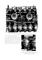
Figure 7-20. Flywheel timing mark locations .
7-16
Back to Top


