TM-9-2815-200-35
ENGINE, WITH CONTAINER:TURBOSUPERCHARGED, DIESEL ,FUEL INJECTION ,90-DEGREE “V” TYPE, AIR - COOLED ,12 - CYLINDER , ASSEMBLY ;MODELS AVDS-1790-2M (2815-856-4996), AVDS-1790-2A AND AVDS-1790-2AM (2815-856-9005)
TECHNICAL MANUAL; DIRECT SUPPORT, GENERAL SUPPORT AND DEPOT MAINTENANCE MANUAL INCLUDING REPAIR PARTS AND SPECIAL TOOLS LISTS
TM-9-2815-200-35 - Page 536 of 779
a .
Turbosupercharger Base, Supports, an d
Tie Rods.
Refer to figures 5-81 through 5-79 .
b. Fuel Inlet and Return Hoses and Crank -
case Breather Tubes.
Refer to figures 5-7 7
through 5-71 .
c.
Exhaust Pipes and Manifolds.
Refer t o
figures 5-78 and 5-70 through 5-68 .
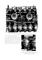
d. Fuel Injector Clamps, Supports, and Tubes .
Refer to figures 5-67 through 5-64 and 4-86, and
(1) through (6), below .
(1) Fuel tubes should be installed in -
dividually and in the sequence listed below to
assure adequate wrench clearance. Beginnin g
with the left bank fuel injector tubes (rear pump
head) install tubes for cylinders 5, 3, 1, 6, 2, and
4 in that order. Install the right bank tubes fo r
cylinders 2, 4, 1, 6, 5, and 3 in that order.
Note.
Injector tubes for cylinders 1, 2, an d
3 right bank, must be routed under the righ t
exhaust manifold between cylinders 2R and 3 R
exhaust port manifold connections .
(2) Special precautions must be taken t o
ensure that all tube connections to a given in -
jection pump port ,
terminates at the prope r
cylinder (figure 4-86). Current replacement fue l
injector tubes have identification tags at eac h
end to assure proper injection pump port con -
nection and cylinder nozzle connection. In -
correct hook up of the injector tubes to a wrong
cylinder or injection pump connection woul d
result in damage to the piston rings and cylinder
walls and severe damage to the engine i f
operated under full load .
(3) Check the alignment of each tube with
its mating fitting. It may be necessary to bend
the tube(s) to gain alignment. The tube MUS T
be aligned in its free state before attempting to
engag e
the fittings ,
to minimize unwante d
stresses .
(4) Start fittings on both ends by hand until
the sleeve is seated. If a wrench is required, only
low torques are necessary to seat the sleeve .
When the sleeve is seated, an increase in torque
will be quite evident. When this point is reached,
draw the nut (each end) up approximately 1 / 6
of a turn (minimum), but not more than 1 / 3 of
a turn (maximum), to complete the tightenin g
operation .
Note .
Overtightening will damage th e
sleeve and cause fuel leaks .
(5) NEVER OVER TIGHTEN whe n
attempting to remedy a fuel leak. Overtightening
will deform the sleeve and eventually lead to tube
failure. It is permissible to loosen the nut, o r
fitting, and re-tighten. This procedure will, i n
many cases, seal the fuel leak. The loosening and
tightening operation tends to re-seat the sleeve ,
thus providing an effective seal. Replace fittings
and / or tubes rather than overtighten to sto p
leaks .
(6) The proper installation and positioning
of the tube clamps is essential to ensure tube lift.
Install all stationary clamps as shown in figure 7-
31. The floating clamps, i.e., the four clamp s
located nearest the pump head, must b e
positioned as specified to ensure maximu m
vibration dampening. The two floating clamp s
on the right bank each support three tubes .
Similar clamps on the left bank support only two
tubes, i.e., tube No’s. 1 and 2, and 5 and 6.
7-24
Back to Top


