TM-9-2815-200-35
ENGINE, WITH CONTAINER:TURBOSUPERCHARGED, DIESEL ,FUEL INJECTION ,90-DEGREE “V” TYPE, AIR - COOLED ,12 - CYLINDER , ASSEMBLY ;MODELS AVDS-1790-2M (2815-856-4996), AVDS-1790-2A AND AVDS-1790-2AM (2815-856-9005)
TECHNICAL MANUAL; DIRECT SUPPORT, GENERAL SUPPORT AND DEPOT MAINTENANCE MANUAL INCLUDING REPAIR PARTS AND SPECIAL TOOLS LISTS
TM-9-2815-200-35 - Page 540 of 779
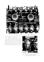
Figure 7-34. Overall view of engine showing progress of engine assembly
at this point.
d. Cooling Fan Vanes and Cooling Fans .
Refer to figures 4-35, 4-34, and 4-88.
7-17.
Engine Accessories
Refer to Table 7-13 for illustrations and assembly instructions. References are listed in
the table.
Table 7-13. Installing Engine Accessories
Component
References
Fuel Pump
Para 7-17a, Figs. 4-3 through 4-1
Turbosupercharger and Lower Shroud Plates
Para 7-17b, Figs. 4-33 through 4-18
Starter
Para 7-17c, Figs. 4-8, 4-7, 5-1, 4-9, 4-4
Time Totalizing Meter
Para 7-17d, Figs. 5-5, 5-4, 4-10
Generator
Para 7-17e, Figs. 7-31, 4-17 through 4-13, 4-11
a. Fuel Pump.
Refer to figures 4-3 through 4-
1.
b.
Turbosupercharger and Lower Shroud
Plates.
Refer to figures 4-33 through 4-18.
c. Starter.
Refer to figures 4-8, 4-7, 5-1, 4-9,
and 4-4 and (1) through (3), below.
(1) Install starter while engine is stil l
mounted on overhaul stand (figs. 4-8 and 4-7).
(2) Install multiple leg sling - 4910-919-
2884 (fig. 5-1) on suitable chain hoist. Install
7-28
hooks of sling in engine lifting eyes and take up
the slack. Remove four bolts and flat washers
securing engine to overhaul stand bracket. Lift
engine and move overhaul stand. Lower engine
on suitable blocks or moveable dolly maintaining
lifting sling hook-up as a precaution against
engin e
tipping during remaining assembl y
operations.
(3) Install starter cradle and support on
engine (fig. 4-9 and 4-4).
Back to Top


