TM-9-2815-200-35
ENGINE, WITH CONTAINER:TURBOSUPERCHARGED, DIESEL ,FUEL INJECTION ,90-DEGREE “V” TYPE, AIR - COOLED ,12 - CYLINDER , ASSEMBLY ;MODELS AVDS-1790-2M (2815-856-4996), AVDS-1790-2A AND AVDS-1790-2AM (2815-856-9005)
TECHNICAL MANUAL; DIRECT SUPPORT, GENERAL SUPPORT AND DEPOT MAINTENANCE MANUAL INCLUDING REPAIR PARTS AND SPECIAL TOOLS LISTS
TM-9-2815-200-35 - Page 537 of 779
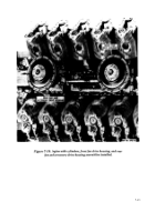
Figure 7-31. Fuel injector clamps, supports, and tubes-installed view .
e. Fuel Injector Nozzle Fuel Return Tubes .
Refer to figures 5-63 through 5-61 .
Note.
Install rigid fuel drain tubes only if they
are in a like new condition, otherwise instal l
current flexible rubber hose as shown in figure 7-
31. The drain tube on hose between cylinde r
numbers 6L and 5L (fig. 7-32 or 7-33) will be
noticeably longer than the other drain tubes o r
hoses due to the position of the fuel injecto r
nozzle and holder assembly drain connector .
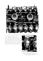
Figure
7-32.
Fuel injector nozzle fuel retur n
tube between cylinder numbers 6 L
and 5L-engines with tubes .
7-25
Back to Top


