TM-9-2815-200-35
ENGINE, WITH CONTAINER:TURBOSUPERCHARGED, DIESEL ,FUEL INJECTION ,90-DEGREE “V” TYPE, AIR - COOLED ,12 - CYLINDER , ASSEMBLY ;MODELS AVDS-1790-2M (2815-856-4996), AVDS-1790-2A AND AVDS-1790-2AM (2815-856-9005)
TECHNICAL MANUAL; DIRECT SUPPORT, GENERAL SUPPORT AND DEPOT MAINTENANCE MANUAL INCLUDING REPAIR PARTS AND SPECIAL TOOLS LISTS
TM-9-2815-200-35 - Page 532 of 779
(3) Check valv e
crankshaft clockwise a s
timing by rotatin g
viewed from rear, ap -
proximately 1 / 8 turn to remove gear backlash ,
then turn counterclockwise until the valve is just
closed. Stop rotating the crankshaft the instan t
the swivel pad becomes free. Observe position of
flywheel timing mark .
When timing mark o n
flywheel is alined within 1 / 8-inch of the timing
pointer, the valve timing is correct. When timing
mark is not alined, withdraw camshaft driv e
shaft, and repeat timing procedure ((2) above )
and again check valve timing. When correc t
valve timing is obtained, install right oil transfer
plug following instructions in figure 7-26 .
Note .
When correct timing cannot b e
obtained as described in (3), above, it may be
necessary to set timing mark 1 / 8 to 1 / 4-inch
out of alinement before installing drive shaft .
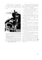
(4) Set cylinder No. 6 intake valve clearance
by rotating crankshaft counterclockwise ap -
proximately 1 / 4 turn in order to have No. 6 R
intake valve rocker arm roller on base circle o f
camshaft. Set intake valve clearance to fina l
0.010-inch setting, using thickness gage blade -
5120-793-7897 as shown in figure 7-22. Torqu e
tighten adjusting screw lock nut to 175 pound -
inches after adjustment .
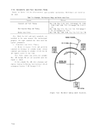
(5) Rotate the crankshaft counterclockwise
approximately 270 degrees from “6L IN T
CLOSE .100 CLR” until flywheel timing mar k
“6R INT CLOSE .100 CLR” is alined wit h
timing pointer. Install the left camshaft and No .
6L valve rocker cover following same procedur e
as outlined for right camshaft and No. 6R valve
rocker cover .
(6) Refer to figure 5-111 and install th e
camshaft gear housing covers, using ne w
mounting gaskets .
b. Fuel Injection Pump and Timing.
Refer t o
figures 4-63 and 4-64 to install coupler half on
fuel injection pump. Torque tighten nut to 900
pound-inches. Refer to figures 4-71, 4-72, 4-65
through 4-68, and 4-75 through 4-81. Additiona l
pertinent instructions are listed below .
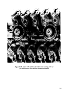
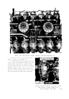
Figure 7-27. Correct position of cylinder 1 R
camshaft lobes (cams) for fuel injectio n
pump installation-installed view.
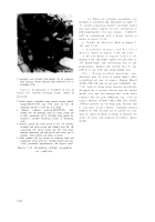
1. Install right oil transfer plug using mechanical puller-
2. Refer to figure 5-112 and install retaining ring.
Figure 7-26. Installing right camshaft oi l
transfer plug .
7-20
Back to Top

