TM-9-2815-200-35
ENGINE, WITH CONTAINER:TURBOSUPERCHARGED, DIESEL ,FUEL INJECTION ,90-DEGREE “V” TYPE, AIR - COOLED ,12 - CYLINDER , ASSEMBLY ;MODELS AVDS-1790-2M (2815-856-4996), AVDS-1790-2A AND AVDS-1790-2AM (2815-856-9005)
TECHNICAL MANUAL; DIRECT SUPPORT, GENERAL SUPPORT AND DEPOT MAINTENANCE MANUAL INCLUDING REPAIR PARTS AND SPECIAL TOOLS LISTS
TM-9-2815-200-35 - Page 535 of 779
7-11.
Nozzle and Holder Assemblies, Cylinder Deflectors, and Shroud s
Refer to Table 7-7 for illustrations and assembly instructions. References are listed i n
the table .
Table 7-7. Nozzle and Holder Assemblies, Cylinder Deflectors, and Shrouds
Component
References
Nozzle and Holder Assemblies
Para 7-11a, Figs. 5-103, 4-165
Shroud Plates and Cylinder Deflectors
Para 7-11b, Figs. 5-102 through 5-97
a. Fuel Injecto r
Nozzle
and
Holder
b.
Camshaft Drive Shrouds and Cylinde r
Assemblies.
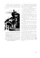
Refer to figures 5-103 and 4-165 .
Deflectors.
Refer to figures 5-102 through 5-97 .
Note.
When installing new gasket on nozzl e
Note.
Removal or installation of shrouds and
assembly, apply a thin coating of grease to the
cylinder deflectors is the same for both left and
gasket to retain gasket in position on nozzl e
right banks of the engine. For instructiona l
assembly .
purposes, the right bank shrouds and cylinde r
deflectors are illustrated .
7-12.
Turbosupercharger Oil Inlet Hose and Fire Extinguisher Tube, Fue l
Injection Pump Oil Inlet Hose, an d
Throttle Control Rods and Leve r
Refer to Table 7-8 for illustrations and assembly instructions. References are listed i n
the table .
Table 7-8. Turbosupercharger Oil Inlet Hose and Fire Extinguisher Tube,
Fuel Injection Pump Oil Inlet Hose, and Throttle
Control Rods and Lever
Component
References
Turbosupercharger Oil Inlet Hose and Fire Extinguisher
Para 7-12a, Figs. 5-90 through 5-88
Tube
Fuel Injection Pump Oil Inlet Hose
Para 7-12b, Figs. 5-87 through 5-84
Throttle Control Rods and Intermediate Lever
Para 7-12c, Figs. 5-83 and 5-82
a.
Turbosupercharger
Oil
Inlet
Hose
and
Fire
b. Fuel Injection Pump Oil Inlet Hose.
Refe r
Extinguisher Tube.
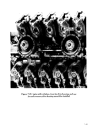
Refer to figures 5-9 0
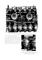
to figures 5-87 through 5-84 .
through 5-88 .
c. Throttle Control Rods and Intermediat e
Throttle Lever.
Refer to figures 5-83 and 5-82 .
7-13. Turbosupercharger Base, Supports, and Tie Rods, Fuel Inlet an d
Return Hoses, Crankcase Breather Tubes ,
Exhaus t
Pipe s
an d
Manifolds, and Fuel Injector Clamps, Supports, and Tube s
Refer to Table 7-9 for illustration s
and assembly instructions. References are listed i n
the table .
Table 7-9. Turbosupercharger Base, Supports, and Tie Rods, Fuel
Inlet and Return Hoses, Crankcase Breather Tubes, Exhaust
Pipes and Manifolds, and fuel Injector Clamps, Supports, and Tubes
Component
References
Turbosupercharger Base, Supports, and Tie Rods
Para 7-13a, Figs. 5-81 through 5-79
Fuel Inlet and Return Hoses and Crankcase Breather
Para 7-13b, Figs. 5-77 through 5-71
Tubes
Exhaust Pipes and Manifolds
Para 7-13c, Figs. 5-78, 5-70 through 5-68
Fuel Injector Clamps, Supports, and Tubes
Para 7-13d, Figs. 5-67 through 5-64, 4-86
Fuel Injector Nozzle Fuel Return Tubes
Para 7-13e, Figs. 5-63 through 5-61
7-23
Back to Top

