TM-9-2815-200-35
ENGINE, WITH CONTAINER:TURBOSUPERCHARGED, DIESEL ,FUEL INJECTION ,90-DEGREE “V” TYPE, AIR - COOLED ,12 - CYLINDER , ASSEMBLY ;MODELS AVDS-1790-2M (2815-856-4996), AVDS-1790-2A AND AVDS-1790-2AM (2815-856-9005)
TECHNICAL MANUAL; DIRECT SUPPORT, GENERAL SUPPORT AND DEPOT MAINTENANCE MANUAL INCLUDING REPAIR PARTS AND SPECIAL TOOLS LISTS
TM-9-2815-200-35 - Page 534 of 779
Figure 7-30
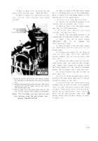
c. Install Rocker Arm Covers.
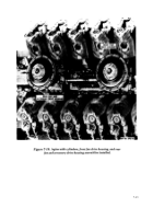
The camshaf t
lobes (cams) for cylinder No. 1R must be down
towards crankshaft, so valve rocker arm roller s
are on base circle of camshaft as shown in figures
7-27 and 7-28 before installing rocker arm cover.
The identification number stamped on rocke r
arm cover must match the number stamped o n
cylinder assembly (fig. 5-105). Rocker ar m
covers must always be installed on their mating
cylinder assemblies .
Note.
For instructional purposes. installation
of rocker arm cover for cylinder No. 1R is used.
Remaining covers are installed in the sam e
manner .
(1) Remove protective cover from fue l
injector nozzle and holder opening in cylinde r
assembly. Apply a light film of sealing com -
pound (MIL-C-10523 Ord.) to valve rocker ar m
cover and install cover. Refer to figure 5-109 and
torque tighten four bolts to 275 to 325 pound -
inches. Refer to figure 5-108 and torque tighten
all bolts and cap screws to 100 pound-inches .
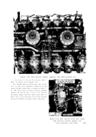
(2) Set valve clearance of No. 1R intak e
valve to 0.010-inch using thickness gage blade -
5210-793-7898 as shown in figure 7-22 .
(3) Set valve clearance of No. 1R exhaus t
valve to 0.025-inch using thickness gage blade -
5210-793-7899 as shown in figure 7-23 .
(4) Rotate crankshaft as necessary t o
position camshaft lobes (cams) in downwar d
position (figs .
7-27 and 7-28) as each of th e
remaining valve rocker arm covers are installed .
7-22
Back to Top


