TM-9-2815-200-35
ENGINE, WITH CONTAINER:TURBOSUPERCHARGED, DIESEL ,FUEL INJECTION ,90-DEGREE “V” TYPE, AIR - COOLED ,12 - CYLINDER , ASSEMBLY ;MODELS AVDS-1790-2M (2815-856-4996), AVDS-1790-2A AND AVDS-1790-2AM (2815-856-9005)
TECHNICAL MANUAL; DIRECT SUPPORT, GENERAL SUPPORT AND DEPOT MAINTENANCE MANUAL INCLUDING REPAIR PARTS AND SPECIAL TOOLS LISTS
TM-9-2815-200-35 - Page 538 of 779
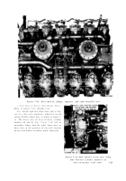
Figure
7-33.
Fuel injector nozzle fuel return hose between cylinder
numbers
6L
and
5L-engines
with
hoses.
7-14. Oil Filler and Indicator Tubes, Rear and Front Shrouds, Throttle Linkage ,
and Fuel Filter s
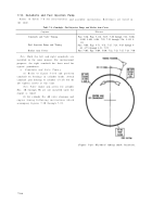
Refer to Table 7-10 for illustrations and assembly instructions .
Table 7-10. Oil Filler and Indicator Tubes, Rear and Front Shrouds,
Throttle Linkage, and Fuel Filters
Component
References
Cylinder Head Plates, Oil Filler Tube, and Oil Level In-
Para 7-14a, Figs. 5-60 through 5-51
dicator Tube
Rear Shroud
Para 7-14b, Figs. 5-50 through 5-48
Front Shroud
Para 7-14c, Figs, 5-47 through 5-42
Throttle Linkage,
Fuel Drain Tubes, Fuel / Water
Para 7-14d, Figs. 5-41 through 5-39, 4-84, 4-85, 5-38
Separator, Secondary Fuel Filter, and Primary Fuel
through 5-34
Filter
7-26
Back to Top


