TM-9-2815-200-35
ENGINE, WITH CONTAINER:TURBOSUPERCHARGED, DIESEL ,FUEL INJECTION ,90-DEGREE “V” TYPE, AIR - COOLED ,12 - CYLINDER , ASSEMBLY ;MODELS AVDS-1790-2M (2815-856-4996), AVDS-1790-2A AND AVDS-1790-2AM (2815-856-9005)
TECHNICAL MANUAL; DIRECT SUPPORT, GENERAL SUPPORT AND DEPOT MAINTENANCE MANUAL INCLUDING REPAIR PARTS AND SPECIAL TOOLS LISTS
TM-9-2815-200-35 - Page 519 of 779
7-7.
Starter and Generator Drive Adapters ,
Vibration Damper, Sending Units ,
Oil Pump, and Oil Tube s
Refer to Table 7-3 for illustration s
and assembly instructions. References are listed i n
the table .
Table 7-3. Starter and Generator Drive Adapters, Vibration Damper,
Sending Units, Oil Pump, and Oil Tubes
Component
References
Generator Drive Adapter and Drive Gearshaft
Para 7-7a, Figs. 5-158 through 5-156
Starter Drive Adapter and Starter Driven Gear
Para 7-7b, Figs. 5-155 through 5-153
Crankshaft Torsional Vibration Damper and Fuel Pump
Para 7-7c, Fig. 5-151
Drive Shaft Coupling
Sending Units, Oil Pump, and Oil Tubes
Para 7-7 and e, Figs. 5-156, 7-10, 5-149, 5-148
a. Generator Drive Adapter and Driv e
Gearshaft.
Refer to figures 5-158 through 5 -
156 .
b. Starter Drive Adapter and Starter Drive n
Gear.
Refer to figures 5-155 through 5-153 .
c. Crankshaft Torsional Vibration Dampe r
and Fuel Pump Drive Shaft Coupling.
Refer t o
figure 5-151 and position crankshaft torsiona l
vibration damper on crankshaft. Tighten fue l
pump drive coupling adapter and vibratio n
damper mounting bolts to 1000 pound-inches .
d. Oil Pressure Sending Unit, Switch, an d
Generator Air Intake Tube Support Brackets .
Refer to figure 5-150 .
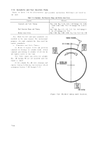
e. Oil Pump and Oil Tubes.
Refer to figure s
5-149 and 5-148. Always use new preforme d
packings on oil transfer tubes when installing the
oil pump assembly. Make certain oil transfe r
tubes aline with openings in crankcase and mesh
oil pump drive gear with accessory drive gea r
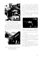
(fig. 7-10). Check oil pump drive gear to b e
certain there is 0.008 to 0.012 inch backlas h
between teeth of pump drive gear and accessory
drive gear .
Figure 7-10. Oil pump mounting flange oi l
discharge locations .
7-7
Back to Top


