TM-9-2815-200-35
ENGINE, WITH CONTAINER:TURBOSUPERCHARGED, DIESEL ,FUEL INJECTION ,90-DEGREE “V” TYPE, AIR - COOLED ,12 - CYLINDER , ASSEMBLY ;MODELS AVDS-1790-2M (2815-856-4996), AVDS-1790-2A AND AVDS-1790-2AM (2815-856-9005)
TECHNICAL MANUAL; DIRECT SUPPORT, GENERAL SUPPORT AND DEPOT MAINTENANCE MANUAL INCLUDING REPAIR PARTS AND SPECIAL TOOLS LISTS
TM-9-2815-200-35 - Page 510 of 779
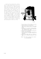
Disassemble
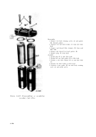
1. Refer to figure 4-60 and 4-62 to remove diaphragm
coupler (A) from injection pump.
2. Remove Woodruff key (B) from pump shaft.
Assemble
1. Position Woodruff key (B) in pump shaft.
2. Refer to figure 4-64 to install diaphragm coupler (A)
on fuel injection pump.
Figure 6-253. Disassembling or assemblin g
fuel injection pump driv e
diaphragm coupler .
b. Cleaning, Inspection, and Repair.
Refer t o
paragraphs 6-2 through 6-4, and (1) and (2) ,
below .
(1)
Drive
splined
coupler.
Refer
to
paragraph 6-42c (7) .
(2) Drive diaphragm coupler.
Whe n
cleaning, Diaphragm must not be immersed i n
fluids or cleaners. Inspect diaphragm (10, fig. B-
16) for cracks, scratches, or mars on rims o r
diaphragms. Inspect diaphragm pack and flang e
coupler (12) keyways for wear or mutilation. I f
diaphragm pack is cracked, do not attempt t o
repair by welding. Replace unserviceable part s
by salvage or replace coupler assembly .
c. Assembly.
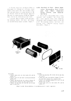
Refer to figures 6-253 and 6-252.
6-68. Rebuild of Fuel Injector Nozzle an d
Holder Assembl y
Refer to paragraphs 4-22 through 4-24 an d
figures 4-163 through 4-165 for rebuild of th e
fuel injector nozzle and holder assembly .
6-69.
Overhaul of Piston Oiler Nozzl e
Assembl y
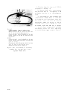
a. Disassembly.
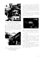
Do not remove nozzles (fig .
6-254) unless the nozzle or holder cannot b e
cleaned without disassembly. To remove nozzles ,
position holder in a soft-jawed vise and remove
nozzles .
b. Cleaning, Inspection, and Repair.
Refer t o
paragraphs 6-2 through 6-4. Make sure oi l
passages in holder and oil holes in nozzles ar e
clean and free of obstruction. Replace nozzle s
and holders as necessary, when oil passages and
holes cannot be cleaned of obstructions .
c. Assembly.
Refer to figure 6-254 to instal l
the nozzle in the holder if removed. Stake nozzles
on three flats, 120 degrees apart .
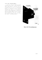
Figure 6-254. Piston oiler nozzle an d
holder assembly .
6-21 6
Back to Top

