TM-9-2815-200-35
ENGINE, WITH CONTAINER:TURBOSUPERCHARGED, DIESEL ,FUEL INJECTION ,90-DEGREE “V” TYPE, AIR - COOLED ,12 - CYLINDER , ASSEMBLY ;MODELS AVDS-1790-2M (2815-856-4996), AVDS-1790-2A AND AVDS-1790-2AM (2815-856-9005)
TECHNICAL MANUAL; DIRECT SUPPORT, GENERAL SUPPORT AND DEPOT MAINTENANCE MANUAL INCLUDING REPAIR PARTS AND SPECIAL TOOLS LISTS
TM-9-2815-200-35 - Page 508 of 779
6-65. Overhaul of Manifold Heater Tubes ,
Filter, and Electrical Component s
a. Disassembly.
Disassemble the manifol d
heater filter following instructions which ac -
company figure 6-251. The heater tubes an d
electrical components were disassembled during
engine disassembly .
b. Cleaning, Inspection, and Repair.
Refer t o
paragraphs 6-2 through 6-4 .
(1)
Heater tubes.
Flush rigid heater tube s
(19, fig. B-21) thoroughly and dry with com -
pressed air. Clean plastic tubes (50) with a
clean dry cloth and blow tubes out with com -
pressed air. Inspect tube fittings for stripped o r
damaged threads. Replace tubes that are split o r
kinked or when fittings are damaged .
(2)
Heater fuel filter.
Replace filter elemen t
if deformed or if foreign material is embedded .
(3)
Electrical components.
Inspect heate r
electrical leads (9, fig. B-21) and ignition unit s
(8) for cracks, continuity, and other damage .
Replace leads and ignition units that fail to pass
continuity test .
c. Assembly.
Refer to figure 6-251. Th e
manifold heater tubes and electrical component s
are assembled during engine assembly, Chapte r
7 .
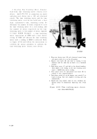
Disassemble
1. Unscrew and separate filter head (A) and filter bowl.
2. Remove and discard filter element (B).
3. Remove and discard preformed packing (C).
Assemble
1. Position a new preformed packing (C) on filter bowl.
2. Position new filter element (B) in bowl
3. Install head (A) on bowl.
Figure 6-251. Disassembling or assemblin g
manifold heater fuel filter .
Section XVIl. OVERHAUL OF FUEL INJECTIO N
PUMP
DRIVE
COUPLERS,
FUEL
INJECTOR NOZZLES, PISTON OILER NOZZLES, AN D
TIME
TOTALIZING
METER
6-66. Genera l
cleaning, inspection, repair, and assembly ac -
This section covers the overhaul of the fue l
company the overhaul instructions. Refer to the
injection pump drive couplers, fuel injecto r
following table (table 6-46) for applicabl e
nozzles, piston oiler nozzles, and time totalizing
illustration s
an d
instructions for overhau l
meter .
Specific instructions on disassembly ,
operations .
6-214
Back to Top


