TM-9-2815-200-35
ENGINE, WITH CONTAINER:TURBOSUPERCHARGED, DIESEL ,FUEL INJECTION ,90-DEGREE “V” TYPE, AIR - COOLED ,12 - CYLINDER , ASSEMBLY ;MODELS AVDS-1790-2M (2815-856-4996), AVDS-1790-2A AND AVDS-1790-2AM (2815-856-9005)
TECHNICAL MANUAL; DIRECT SUPPORT, GENERAL SUPPORT AND DEPOT MAINTENANCE MANUAL INCLUDING REPAIR PARTS AND SPECIAL TOOLS LISTS
TM-9-2815-200-35 - Page 515 of 779
b. Piston Oiler Nozzles.
Refer to figure 5 -
180 .
c. Crankshaft and Connecting Rod Assembly .
Refer to figures 5-179 through 5-175 and to the
instructions given in (1) through (3), below .
(1)
Main bearing caps.
Coat outer edge s
of the bearing cap and machined surfaces of th e
crankcase webs with engine oil to facilitat e
installation of caps .
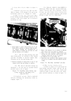
1. Install number 4 (center) thrust bearing cap (A) and
bearing half in position on crankcase studs (tie rods).
Use
crankcase
spreading
tool
(B)-5120-575-7767
to
spread crankcase so bearing caps will slide over studs
and into position in the crankcase.
Note .
Be sure main bearing caps an d
main bearing halves are installed in their original
positions according to location number iden -
tification on the cap and bearing half .
2. Install the remaining six bearing halves in caps (C) and
similarly install caps and bearings in crankcase.
Note.
The side of each main bearing cap
identified as “fly end” must be installed toward
flywheel end or rear of engine .
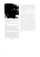
Figure 7-2. Installing main bearing cap s
using crankcase spreading tool -
Note.
End play should be from 0.00740 to
0.019-inch. When end play exceeds 0.019-inch ,
remove bearing caps and crankshaft. Instal l
bearing cap and recheck thrust bearing bor e
(para 6-9d). Then install crankshaft and recheck
end play to make sure it is within limits.
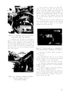
1. Mount a dial indicator (A) on crankcase so indicator
point contacts drive gear flange on crankshaft.
2. Using a heavy duty screwdriver, wedged between main
bearing cap and crankshaft counterweight, push
crankshaft toward front end (B) of crankcase.
3. Set indicator (C) on zero reading (“0”).
4. Using heavy duty screwdriver, push crankshaft toward
the rear (D) of crankcase and check indicator end play
reading.
Figure 7-3. Checking crankshaft end play .
(3)
Main bearing attaching parts .
(a) Refer to figure 5-173 and install al l
main bearing cap plate washers and nuts. Do not
torque tighten nuts at this time. Check an d
record the height of each stud using a flat surface
plate and dial indicator as shown in figure 7-4 .
(2)
Crankshaft end play.
Check crankshaf t
end play following the instructions which ac -
company figure 7-3 .
7- 3
Back to Top


