TM-9-2815-200-35
ENGINE, WITH CONTAINER:TURBOSUPERCHARGED, DIESEL ,FUEL INJECTION ,90-DEGREE “V” TYPE, AIR - COOLED ,12 - CYLINDER , ASSEMBLY ;MODELS AVDS-1790-2M (2815-856-4996), AVDS-1790-2A AND AVDS-1790-2AM (2815-856-9005)
TECHNICAL MANUAL; DIRECT SUPPORT, GENERAL SUPPORT AND DEPOT MAINTENANCE MANUAL INCLUDING REPAIR PARTS AND SPECIAL TOOLS LISTS
TM-9-2815-200-35 - Page 516 of 779
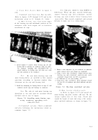
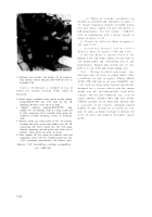
Figure 7-4. Measuring main bearing stu d
stretch using dial indicator .
(b) Refer to figures 5-172 and 5-171 and
install crankcase tie rods but do not torqu e
tighten at this time. Refer to paragraph 7-6c .
(c) Starting at number 4 main thrus t
bearing, and alternating right and left, suc -
cessively torque tighten all main bearing stu d
nuts to 500 pound-inches, then, following th e
same procedure and sequence, torque tighten al l
nuts
to
a
final
torque
of
700
to
825
pound-
inche s
(d) Following the same procedure as (a) ,
above, recheck stud height and apply sufficien t
additional torque to each nut, as in (c), above, to
aline nut slot with drilled hole in stud, and to
obtain a stud stretch of 0.019 to 0.022-in. Do not
exceed 0.024-in. Stud stretch is defined as the
difference between the original height recorded
in (a) above, and height observed after nuts have
bee n
torqu e
tightened ,
refer t o
torqu e
specifications (para 6-7) .
7-6 .
Accessory Drive Gear, Crankshaf t
Oil Seal, Transmission Adapter ,
and Flywhee l
Refer to Table 7-2 for illustrations an d
assembly instructions .
References are listed in
the table .
Table 7-2. Accessory Drive Gear, Crankshaft Oil Seal, Transmission Adapter,
and Flywheel
Component
Reference
Accessory Drive Gear Crankshaft Oil Seal Housing
Para 7-6a and b, Figs. 5-169, 7-5, 5-168, 7-6, 7-7, 5-167
through 5-165
Transmission Adapter, Flywheel, and Transmission Drive
Para 7-6e through g, Figs. 5-182, 5-163, 7-8, 5-159, 7-9
Gearshaft Assembly
a. Accessory Drive Gear .
(2)
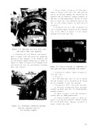
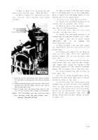
Checking accessory drive gear backlash .
(1)
Install accessory drive gear.
Refer t o
Check backlash between accessory drive gea r
figure 5-169 and alternately tighten 12 bolts to
teeth and starter drive idler gear teeth as shown
draw drive gear on to crankshaft flange .
in figure 7-5. Backlash should be from 0.004 to
Note .
Always use accessory drive gear ,
0.009-inch. Check backlash between accessor y
FSN 2815-861-3829 (part number - 10898778 )
drive gear teeth and generator drive idler gear in
during engine assembly. This gear can b e
the same manner .
identified by measuring the length of the gea r
teeth, which are approximately 1-15 / 32-inch .
7-4
Back to Top


