TM-9-2815-205-24 - Page 439 of 856
INSTALLATION
1.
Apply water displacing compound or equivalent to threads and to bolt head contact area (underside) of all
flywheel-fastening bolts (Figure 4, Item 4). Fill threads completely with compound and remove excess.
2.
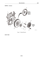
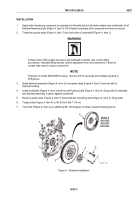
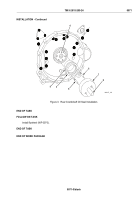
Thread two guide studs (Figure 4, Item 7) into bolt holes of crankshaft (Figure 4, Item 1).
WARNING
Components of this engine are heavy and awkward to handle. Use correct lifting
procedures, indicated lifting devices, and/or assistance from other personnel. Failure to
comply may result in injury to personnel.
NOTE
Flywheel on model 5063-5299 is heavy. Use two 3/8-16 eye bolts and multiple leg sling to
lift flywheel.
3.
Guide flywheel assembly (Figure 4, Item 2) over guide studs (Figure 4, Item 7) and into bell of
flywheel housing.
4.
Install scuff plate (Figure 4, Item 3) and four self-locking bolts (Figure 4, Item 4). Snug bolts to hold plate
and flywheel assembly in place against crankshaft.
5.
Remove guide studs (Figure 4, Item 7) and install two remaining bolts (Figure 4, Item 4). Snug bolts.
6.
Torque bolts (Figure 4, Item 4) to 48–52 lb-ft (65–71 N·m).
7.
Turn bolts (Figure 4, Item 4) an additional 90–120 degrees to obtain required clamping force.
1
3
4
2
7
MODELS
5063-5392
5063-5393
5063-539L
2
7
MAINT_189
Figure 4.
Flywheel Installation.
TM 9-2815-205-24
0070
0070-7
Back to Top

