TM-9-2815-205-24 - Page 431 of 856
INSTALLATION
NOTE
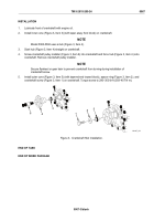
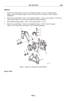
Four screws (Figure 1, Item 12) must be temporarily installed prior to torquing screws
(Figure 1, Item 9) to ensure proper alignment of front support (Figure 1, Item 7).
1.
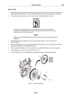
Install front support (Figure 1, Item 7), four screws (Figure 1, Item 12), two screws (Figure 1, Item 9), and
two new lockwashers (Figure 1, Item 10) on lower front cover (Figure 1, Item 6). Torque screws
(Figure 1, Item 9) to 46–50 lb-ft (62–68 N·m). Remove four screws (Figure 1, Item 12).
2.
Slide preformed packing (Figure 1, Item 11) on support (Figure 1, Item 7).
3.
Install engine support (Figure 1, Item 8), two screws (Figure 1, Item 3), two new lockwashers
(Figure 1, Item 4), and cap (Figure 1, Item 5) on preformed packing (Figure 1, Item 11) and front support
(Figure 1, Item 7). Torque screws to 46–50 lb-ft (62–68 N·m).
4.
Install bracket (Figure 1, Item 1), four screws (Figure 1, Item 12), four new lockwashers (Figure 1, Item 13),
and eight flat washers (Figure 1, Item 2) on front support (Figure 1, Item 7). Torque screws to 46–50 lb-ft
(62–68 N·m).
END OF TASK
FOLLOW ON TASK
1.
Install crankshaft hub (WP 0067).
2.
Install solenoid valve and bracket (WP 0043).
END OF TASK
END OF WORK PACKAGE
TM 9-2815-205-24
0069
0069-3/blank
Back to Top


