TM-9-2815-205-24 - Page 434 of 856
REMOVAL
1.
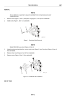
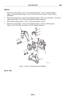
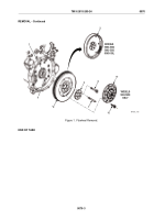
On model 5063-5299, remove eight bolts (Figure 1, Item 6) and clutch plate assembly (Figure 1, Item 5)
from flywheel assembly (Figure 1, Item 2). Discard bolts.
2.
Remove two self-locking bolts (Figure 1, Item 4) from flywheel assembly (Figure 1, Item 2) and crankshaft
(Figure 1, Item 1). Thread two guide studs (Figure 1, Item 7) in locations where bolts were removed.
Discard bolts.
3.
Remove remaining four self-locking bolts (Figure 1, Item 4) and scuff plate (Figure 1, Item 3).
Discard bolts.
WARNING
Components of this engine are heavy and awkward to handle. Use correct lifting
procedures, indicated lifting devices, and/or assistance from other personnel. Failure to
comply may result in injury to personnel.
NOTE
Flywheel on model 5063-5299 is heavy. Use two 3/8-16 eye bolts and multiple leg sling to
lift flywheel.
4.
Break flywheel assembly (Figure 1, Item 2) loose from crankshaft and slide off guide studs.
5.
Remove two guide studs (Figure 1, Item 7) from crankshaft (Figure 1, Item 1).
TM 9-2815-205-24
0070
0070-2
Back to Top

