TM-9-2815-205-24 - Page 428 of 856
REMOVAL
1.
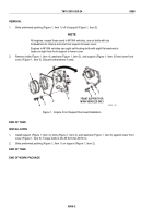
Slide preformed packing (Figure 1, Item 1) off of support (Figure 1, Item 2).
NOTE
All engines, except those used in M1064 vehicles, use six bolts with six
lockwashers to retain a six-hole front support to lower cover.
Engines in M1064 vehicles use eight self-locking bolts with eight flat washers to
retain an eight-hole front support to lower cover.
2.
Remove bolts (Figure 1, Item 4), washers (Figure 1, Item 3), and support (Figure 1, Item 2) from lower front
cover (Figure 1, Item 5). Discard lockwashers if used.
4
3
2
5
2
3
4
1
FRONT SUPPORT FOR
M1064 VEHICLES ONLY
MAINT_184
Figure 1.
Engine Front Support Removal/Installation.
END OF TASK
INSTALLATION
1.
Install support (Figure 1, Item 2), bolts (Figure 1, Item 4), and washers (Figure 1, Item 3) against lower front
cover (Figure 1, Item 5). Torque bolts to 46–50 lb-ft (62–68 N·m).
2.
Slide preformed packing (Figure 1, Item 1) on support (Figure 1, Item 2).
END OF TASK
END OF WORK PACKAGE
TM 9-2815-205-24
0068
0068-2
Back to Top


