TM-9-2815-205-24 - Page 425 of 856
INSTALLATION
1.
Lubricate front of crankshaft with engine oil.
2.
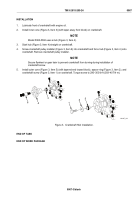
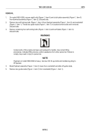
Install inner cone (Figure 3, Item 3) (with taper away from block) on crankshaft.
NOTE
Model 5063-5392 uses a hub (Figure 3, Item 4).
3.
Start hub (Figure 3, Item 4) straight on crankshaft.
4.
Screw crankshaft pulley installer (Figure 3, Item 6) into crankshaft and force hub (Figure 3, Item 4) onto
crankshaft. Remove crankshaft pulley installer.
NOTE
Secure flywheel or gear train to prevent crankshaft from turning during installation of
crankshaft screw.
5.
Install outer cone (Figure 3, Item 5) (with tapered end toward block), spacer ring (Figure 3, Item 2), and
crankshaft screw (Figure 3, Item 1) on crankshaft. Torque screw to 290–300 lb-ft (393–407 N·m).
4
3
6
5
1
2
MAINT_183
Figure 3.
Crankshaft Hub Installation.
END OF TASK
END OF WORK PACKAGE
TM 9-2815-205-24
0067
0067-3/blank
Back to Top

