TM-9-2815-205-24 - Page 422 of 856
REMOVAL
NOTE
Secure flywheel or gear train to prevent crankshaft from turning during removal of
crankshaft screw.
1.
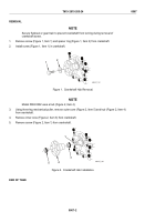
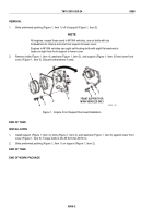
Remove screw (Figure 1, Item 1) and spacer ring (Figure 1, Item 2) from crankshaft.
2.
Slide sleeve (Figure 1, Item 3) off crankshaft.
1
3
2
MAINT_180
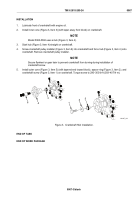
Figure 1.
Camshaft Spacer Removal/Installation.
END OF TASK
INSTALLATION
NOTE
Secure flywheel or gear train to prevent crankshaft from turning during installation of
crankshaft screw.
Install sleeve (Figure 1, Item 3), spacer ring (Figure 1, Item 2), and screw (Figure 1, Item 1) on crankshaft.
Torque screw to 290–300 lb-ft (393–407 N·m).
END OF TASK
END OF WORK PACKAGE
TM 9-2815-205-24
0066
0066-2
Back to Top


