TM-9-2815-205-24 - Page 424 of 856
REMOVAL
NOTE
Secure flywheel or gear train to prevent crankshaft from turning during removal of
crankshaft screw.
1.
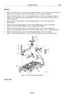
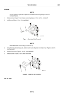
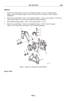
Remove screw (Figure 1, Item 1) and spacer ring (Figure 1, Item 2) from crankshaft.
2.
Install screw (Figure 1, Item 1) in crankshaft.
1
2
MAINT_181
Figure 1.
Crankshaft Hub Removal.
NOTE
Model 5063-5392 uses a hub (Figure 2, Item 4).
3.
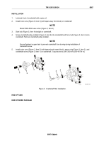
Using three-leg mechanical puller, remove outer cone (Figure 2, Item 5) and hub (Figure 2, Item 4)
from crankshaft.
4.
Remove inner cone (Figure 2, Item 3) from crankshaft.
5.
Remove screw (Figure 2, Item 1) from crankshaft.
1
3
5
4
MAINT_182
Figure 2.
Crankshaft Hub Installation.
END OF TASK
TM 9-2815-205-24
0067
0067-2
Back to Top

