TM-9-2815-205-24 - Page 414 of 856
REMOVAL
1.
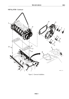
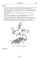
Remove two bolts (Figure 1, Item 20) and two lockwashers (Figure 1, Item 19) fastening oil pump inlet tube
(Figure 1, Item 1) to bottom of lower front cover (Figure 1, Item 15). Discard lockwashers.
2.
Remove two screws (Figure 1, Item 11), two lockwashers (Figure 1, Item 12), and two special washers
(Figure 1, Item 13) fastening support bracket (Figure 1, Item 17) to main bearing cap (Figure 1, Item 14).
Discard lockwashers.
3.
Remove oil pump inlet tube (Figure 1, Item 1) and gasket (Figure 1, Item 18) from cylinder block.
Discard gasket.
4.
Remove two self-locking bolts (Figure 1, Item 2), two flat washers (Figure 1, Item 3), and strainer
(Figure 1, Item 4) from inlet tube (Figure 1, Item 1). Discard self-locking bolts.
5.
Remove two screws (Figure 1, Item 7), two lockwashers (Figure 1, Item 6), two special washers
(Figure 1, Item 5), and bracket (Figure 1, Item 10) from inlet tube (Figure 1, Item 1). Discard lockwashers.
6.
Remove two locknuts (Figure 1, Item 16), eight flat washers (Figure 1, Item 9), two screws
(Figure 1, Item 8), and bracket (Figure 1, Item 17) from bracket (Figure 1, Item 10). Discard locknuts.
20
5
11
12
13
6
7
4
3
2
1
8
9
10
9
17
16
19
18
15
14
MAINT_178
Figure 1.
Oil Inlet Tube Removal/Installation.
END OF TASK
TM 9-2815-205-24
0064
0064-2
Back to Top


