TM-9-2815-205-24 - Page 406 of 856
INSTALLATION - Continued
NOTE
Model 5063-5299, uses two front blower-to-block bolts which are 5/16 inch longer. These
bolts and washers are installed during the igniter and air pump assembly installation.
10.
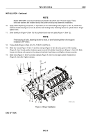
Apply water displacing compound, or equivalent, to four self-locking bolts (Figure 4, Item 4). Install four
hardened washers (Figure 4, Item 5) and four self-locking bolts, fastening blower to cylinder block. Finger
tighten bolts.
11.
Drive dowel pin (Figure 4, Item 10) into cylinder block rear end plate (Figure 4, Item 12).
NOTE
Final torquing of bolts, attaching blower to block, is done following blower drive support
installation (WP 0060).
12.
Torque bolts (Figure 4, Item 4) to 10–15 lb-ft (14–20 N·m).
13.
Slide two hoses (Figure 4, Item 1) and two clamps (Figure 4, Item 2) onto governor link housing
(Figure 4, Item 3) and position between governor and left cylinder head sleeve (Figure 4, Item 24). Slide
hoses and clamps onto governor housing and cylinder head sleeve and tighten clamps securely.
14.
Slide hose (Figure 4, Item 7) and two clamps (Figure 4, Item 8) onto right cylinder head sleeve
(Figure 4, Item 25). Tighten clamps.
1
24
2
3
2
1
5
4
6
12
11
10
7 25
8
24
MAINT_176a
Figure 4.
Blower Installation.
END OF TASK
TM 9-2815-205-24
0062
0062-6
Back to Top


