TM-9-2815-205-24 - Page 398 of 856
INSTALLATION - Continued
NOTE
If spring pack assembly comes apart during storage or removal, refer to (WP 0087) for
assembly instructions.
5.
Install spring pack assembly (Figure 3, Item 5) in side of governor housing (Figure 3, Item 4). Using face
spanner socket wrench, tighten packing nut (Figure 3, Item 6).
NOTE
Torque bolts on cover (Figure 3, Item 9) during engine tune-up (WP 0100).
6.
Install new gasket (Figure 3, Item 10), cover (Figure 3, Item 9), two new copper flat washers
(Figure 3, Item 8), and two bolts (Figure 3, Item 7) on governor housing (Figure 3, Item 4).
7.
Place new gasket (Figure 3, Item 3) and governor cover (Figure 3, Item 2) on top of governor housing
(Figure 3, Item 4). Ensure control link lever (Figure 3, Item 23) engages pin (Figure 3, Item 21) on
differential lever (Figure 3, Item 22); pin (Figure 3, Item 19) in speed control shaft enters slot in differential
lever; and, pin (Figure 3, Item 20) in stop lever shaft (Figure 3, Item 18) engages between stop on underside
of cover and against vertical extension of control link lever.
8.
Install governor cover (Figure 3, Item 2) and seven screw assemblies (Figure 3, Item 1) on governor
housing (Figure 3, Item 4). Tighten screws.
1
18
9
8
7
19
20
21
22
23
3
4
6
10
5
2
MAINT_173
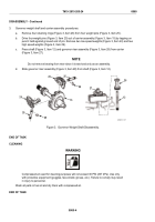
Figure 3.
Governor Cover and Throttle Rod Installation.
END OF TASK
TM 9-2815-205-24
0061
0061-4
Back to Top

