TM-9-2815-205-24 - Page 404 of 856
INSTALLATION
NOTE
Remove four bolts and flat washers used to temporarily fasten rear end plate to
blower housing.
Insert second screw in right side of governor housing before placing housing on
blower.
1.
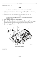
For model 5063-5299, install new gasket (Figure 3, Item 14), governor assembly (Figure 3, Item 15), six flat
washers (Figure 3, Item 18), six new lockwashers (Figure 3, Item 17), and six screws (Figure 3, Item 19) on
blower (Figure 3, Item 13) rear end plate. Torque screws to 20–24 lb-ft (27–33 N·m).
2.
For models 5063-5392, 5063-5393, and 5063-539L, install new gasket (Figure 3, Item 14), governor
assembly (Figure 3, Item 15), six flat washers (Figure 3, Item 18), six new lockwashers (Figure 3, Item 17),
short screw (Figure 3, Item 16), and five screws (Figure 3, Item 19) on blower (Figure 3, Item 13) rear end
plate. Torque screws to 20–24 lb-ft (27–33 N·m).
CAUTION
Excessive protrusion of blower housing with respect to end plate could cause distortion
when torquing down blower resulting in rotor to housing contact.
3.
Measure distance from bottom of rear end plate to bottom of blower housing. Protrusion of blower housing
with respect to end plate must not be more than 0.001 inch (0.00254 mm) above to 0.004 inch
(0.01016 mm) below end plate.
4.
Using gasket adhesive, affix new gasket (Figure 3, Item 20) to cylinder block rear end plate
(Figure 3, Item 12).
5.
Place new seal (Figure 3, Item 22) in groove in top of cylinder block.
6.
Using gasket adhesive, affix two new gaskets (Figure 3, Item 21) to top of cylinder block.
7.
Install two guide studs (Figure 3, Item 23) in blower bolt holes in cylinder block.
8.
Install two clamps (Figure 3, Item 7) and hose (Figure 3, Item 8) on right fuel rod cover (Figure 3, Item 9).
WARNING
Never crawl under equipment when performing maintenance unless equipment is securely
blocked. Keep clear of equipment when it is being raised or lowered. Do not allow heavy
components to swing while suspended by lifting device. Exercise caution when working
near a cable or a chain under tension as equipment may drop or shift. Failure to comply
may result in injury to personnel.
9.
Using two 3/8-16 eye bolts and multiple leg sling, lower blower and governor assembly (Figure 3, Item 6)
over guide studs (Figure 3, Item 23). Push blower away from cylinder block rear end plate
(Figure 3, Item 12) while lowering into position. Remove two guide studs.
TM 9-2815-205-24
0062
0062-4
Back to Top


