TM-9-2815-205-24 - Page 397 of 856
REMOVAL - Continued
7.
Repeat Steps 4–6 for left cylinder head.
11
4
12
14
13
17
16
15
MAINT_172
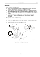
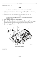
Figure 2.
Lower Connecting Link Removal/Installation.
END OF TASK
INSTALLATION
1.
On right cylinder, install right upper connecting link (Figure 2, Item 17) from inside governor housing
(Figure 2, Item 4) and then install shoulder pin (Figure 2, Item 11). Tighten pin securely.
2.
Connect lower connecting link (Figure 2, Item 15) to upper connecting link (Figure 2, Item 17) with new
locknut (Figure 2, Item 16). Tighten nut securely.
3.
Install pin (Figure 2, Item 14) through injector control tube lever (Figure 2, Item 13) and then through lower
connecting link (Figure 2, Item 15) with cotter pin hole toward front. Install new cotter pin (Figure 2, Item 12)
in hole of pin (Figure 2, Item 14).
4.
Repeat Steps 1–3 for left cylinder head.
TM 9-2815-205-24
0061
0061-3
Back to Top

