TM-9-2815-205-24 - Page 387 of 856
DISASSEMBLY
1.
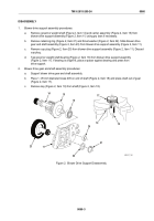
Blower drive support assembly procedures:
a.
Remove governor weight shaft (Figure 2, Item 14) and carrier assembly (Figure 2, Item 15) from
blower drive support assembly (Figure 2, Item 11) using pry bars if necessary.
b.
Remove retaining ring (Figure 2, Item 21) and thrust washer (Figure 2, Item 22). Slide blower drive
gear and shaft assembly (Figure 2, Item 23) from blower drive support assembly (Figure 2, Item 11).
c.
Remove cup plug (Figure 2, Item 20) from blower drive support assembly (Figure 2, Item 11). Discard
cup plug.
d.
Tap governor weight shaft bearing (Figure 2, Item 16) from blower drive support assembly
(Figure 2, Item 11). If bearing is a tight fit, place a spacer against bearing and press from
drive support.
2.
Blower drive gear and shaft assembly procedures:
a.
Support blower drive gear and shaft assembly.
b.
Place 1-1/8 inch diameter brass drift on end of shaft (Figure 2, Item 18) and press shaft out of gear
(Figure 2, Item 17).
c.
Remove key (Figure 2, Item 19) from shaft (Figure 2, Item 18).
14
16
18
19
20
23
15
21
22
11
17
MAINT_166
Figure 2.
Blower Drive Support Disassembly.
TM 9-2815-205-24
0060
0060-3
Back to Top

