TM-9-2815-205-24 - Page 384 of 856
REMOVAL
CAUTION
Use care when removing tachometer adapter. Tachometer drive shaft is fragile and subject
to breakage.
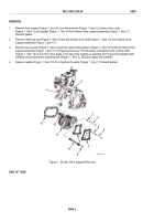
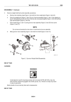
Remove two bolts (Figure 1, Item 3), two lockwashers (Figure 1, Item 2), tachometer adapter
(Figure 1, Item 5), and gasket (Figure 1, Item 6) from flywheel housing. Discard lockwashers and gasket.
2
5
6
3
3
2
5
6
1
2
3
2
3
4
MAINT_164
Figure 1.
Tachometer Drive Replacement Removal/Installation.
END OF TASK
INSTALLATION
1.
Install new gasket (Figure 1, Item 6), tachometer adapter (Figure 1, Item 5), two new lockwashers
(Figure 1, Item 2), and two bolts (Figure 1, Item 3) on flywheel housing. Do not tighten bolts.
2.
Insert tachometer alignment tool (Figure 1, Item 4) into tachometer adapter (Figure 1, Item 5) and over end
of drive shaft (Figure 1, Item 1). Adjust adapter so there is no drive shaft binding on inside diameter of
tachometer alignment tool when crankshaft is rotated one revolution.
3.
Torque bolts (Figure 1, Item 3) to 13–17 lb-ft (18–23 N·m).
4.
Remove tachometer alignment tool (Figure 1, Item 4) from tachometer adapter (Figure 1, Item 5).
END OF TASK
END OF WORK PACKAGE
TM 9-2815-205-24
0059
0059-2
Back to Top


