TM-9-2815-205-24 - Page 380 of 856
REMOVAL
NOTE
Three air inlet housing screws were removed during removal of fuel line clip and air
pump bracket.
1.
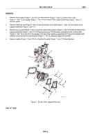
Remove four short screws (Figure 1, Item 6), two mid-sized screws (Figure 1, Item 1), three long screws
(Figure 1, Item 2), nine lockwashers (Figure 1, Item 3), nine flat washers (Figure 1, Item 4), air inlet housing
(Figure 1, Item 9), and screen (Figure 1, Item 7) from blower (Figure 1, Item 8). Discard lockwashers
and screen.
2.
Remove transducer (Figure 1, Item 5) from air inlet housing (Figure 1, Item 9).
1
2
3
3
3
4
4
4
5
6
7
9
8
MAINT_163
Figure 1.
Air Inlet Housing Removal/Installation.
END OF TASK
TM 9-2815-205-24
0058
0058-2
Back to Top


