TM-9-2815-205-24 - Page 390 of 856
ASSEMBLY
1.
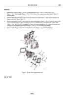
Governor weight shaft and carrier assembly procedures:
a.
Lubricate governor weight shaft (Figure 4, Item 12) with engine oil and slide governor riser assembly
(Figure 4, Item 28) over shaft with bearing end toward serrated end of shaft. Pack bearing
(Figure 4, Item 30) with grease.
b.
Using governor weight spacer (Figure 4, Item 31), press weight shaft (Figure 4, Item 12) into carrier
(Figure 4, Item 15). Spacer will properly position carrier on shaft.
NOTE
Governor high speed weights are identified by long cam arm and low speed weights
are identified by short cam arm.
c.
Place two low speed weights (Figure 4, Item 24) on opposite sides of carrier assembly
(Figure 4, Item 15). Drive grooved end of two weight pins (Figure 4, Item 25) through larger hole in
carrier, through weight, and then through smaller hole in carrier. Drive knurled end of pin until groove
is clear of carrier assembly.
d.
Install two retainer rings (Figure 4, Item 26) on two weight pins (Figure 4, Item 25).
e.
Install two high speed weights (Figure 4, Item 29) in same manner as installing low speed weights.
Refer to Steps 1.c.–1.d.
.
12
26
25
28
15
29
24
30
31
15
26
25
MAINT_168
Figure 4.
Governor Weight Shaft Assembly.
2.
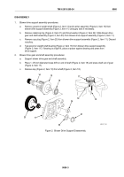
Blower drive support assembly procedures:
a.
Lubricate drive gear shaft (Figure 5, Item 18) with engine oil and install in blower drive
support assembly (Figure 5, Item 11).
b.
Install thrust washer (Figure 5, Item 22) and retaining ring (Figure 5, Item 21) on end of blower drive
gear shaft (Figure 5, Item 18).
c.
Install key (Figure 5, Item 19) in shaft (Figure 5, Item 18).
d.
Support blower drive support assembly (Figure 5, Item 11). Lubricate inside diameter of blower drive
gear (Figure 5, Item 17) and start gear straight on shaft (Figure 5, Item 18), with keyway in gear
aligned with key in shaft. Place governor weight spacer (Figure 5, Item 31) over gear and press gear
on shaft until there is 0.004 to 0.012 inch (0.10 to 0.30 mm) clearance between gear and
drive support.
e.
Support blower drive support assembly (Figure 5, Item 11), with inner face up. Place governor weight
shaft bearing (Figure 5, Item 16), numbered side up, on bore of drive support. Using a sleeve against
outer race, press bearing against shoulder of blower drive support.
TM 9-2815-205-24
0060
0060-6
Back to Top


