TM-9-2815-205-24 - Page 552 of 856
REPAIR OR REPLACEMENT - Continued
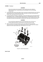
(15) Install cylinder depth gage (Figure 19, Item 90) in injector tube. Using profile gage
(Figure 19, Item 91), pre-measure distance from fire deck to gage (final reading will have to be
within +/- 0.014 inch (0.36 mm) of fire deck).
(16)
Wash interior of injector tube (Figure 19, Item 84) to prepare for second reaming operation.
(17) Apply a few drops of cutting oil on bevel seat of injector tube (Figure 19, Item 84). Lower bevel
reamer (Figure 19, Item 92) carefully into injector tube until it contacts bevel seat.
(18) For trial cut, turn bevel reamer (Figure 19, Item 92) steadily without applying any downward
force. Remove reamer, clean out chips, and observe what portion of injector nut seat was cut.
(19) Proceed with reaming and withdraw bevel reamer occasionally to observe progress.
(20) Continue reaming until shoulder of spray tip is within +/- 0.014 inch (0.36 mm) of fire deck. Use
gages (Figure 19, Items 91 and 90) to measure distance.
(21) Wash interior of injector tube (Figure 19, Item 84).
10.
Throttle delay housing assembly inspection procedures:
Inspect throttle delay check valve for leakage. Fill throttle delay cylinder with fuel oil and watch check
valve for leakage while slowly moving piston into housing. If more than a drop of leakage occurs,
replace check valve.
90
91
84
92
84
MAINT_266
Figure 19.
Fuel Injector Depth Gage Check and Injector Tube Reaming.
END OF TASK
ASSEMBLY
NOTE
Coat plugs and fittings with sealing compound before installing.
Drive expansion plugs flush to 0.0625 inch (1.588 mm) below surface of
cylinder head.
1.
If removed, install three new expansion plugs (Figure 20, Item 37) in sides of cylinder head, one plug on
inboard side and two plugs on outboard side.
2.
If removed, install sleeve (Figure 20, Item 40) on inboard side of cylinder head at rear. Coat sleeve with
sealing compound and drive into bore until it protrudes 3/8 inch.
TM 9-2815-205-24
0083
0083-22
Back to Top


