TM-9-2815-205-24 - Page 557 of 856
ASSEMBLY - Continued
21
22
27
23
28
20
20
19
26
24
25
23
20
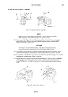
MAINT_272
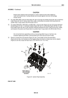
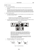
Figure 25.
Cylinder Head Cam Follower Installation.
25.
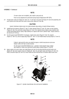
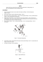
Measure clearance between cam follower guide (Figure 26, Item 28) and cam follower legs using thickness
gages. Clearance must be at least 0.005 inch (0.13 mm).
26.
If clearance is too small, slightly loosen screws (Figure 26, Item 21) and tap corners of guide
(Figure 26, Item 28) with brass drift. Torque screws again after proper adjustment.
21
28
0.005 in.
(0.12 mm)
MAINT_273
Figure 26.
Cylinder Head Cam Follower Guide Clearance Check.
TM 9-2815-205-24
0083
0083-27
Back to Top


