TM-9-2815-205-24 - Page 556 of 856
ASSEMBLY - Continued
NOTE
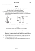
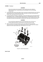
The limits for exhaust valve protrusion with respect to cylinder head is shown
(Figure 24).
g.
With bottom of cylinder head facing up, measure exhaust valve protrusion beyond fire deck using
cylinder depth gage (Figure 24, Item 93). If out of limits, regrind or replace insert and exhaust valve.
MAXIMUM OF 0.024 in.
(0.61 mm) BELOW HEAD
[0.037 in. (0.94mm) USED PARTS]
93
MAINT_271
Figure 24.
Cylinder Head Exhaust Valve Depth Check.
NOTE
Before installing cam followers, immerse in Cindol 1411 metal quenching oil
heated to 100–125°F (38–52°C) for one hour for initial lubrication of cam roller pins
and bushings. Rotate cam rollers during soaking period to purge air from bushing
and roller area.
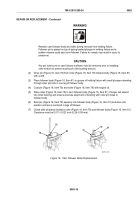
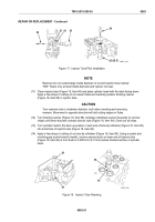
Install used cam followers and push rods in original locations.
20.
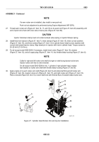
Assemble lower spring seat (Figure 25, Item 24), spring (Figure 25, Item 25), upper spring seat
(Figure 25, Item 26), and push rod nut (Figure 25, Item 19) on nine push rods (Figure 25, Item 20).
21.
Install nine spring retainers (Figure 25, Item 27) in bores from top of cylinder head.
22.
Slide nine push rod (Figure 25, Item 20) assemblies in cylinder head from bottom.
NOTE
Install cam followers with oil hole away from exhaust valves.
23.
Slide nine cam followers (Figure 25, Item 23) in cylinder head from bottom.
CAUTION
Cam follower must not be cocked in bore. With cam follower guide installed, bottom of cam
follower body must be flush with fire deck.
24.
Install three cam follower guides (Figure 25, Item 28), six new lockwashers (Figure 25, Item 22), and six
screws (Figure 25, Item 21) on cylinder head. Torque screws to 144–180 lb-in (16–20 N·m).
TM 9-2815-205-24
0083
0083-26
Back to Top


