TM-9-2815-205-24 - Page 562 of 856
NOTE
Injectors which were removed from engine should be tested (refer to Testing, Steps 1–6)
prior to any disassembly to avoid unnecessary repair.
DISASSEMBLY
1.
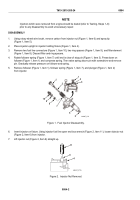
Using rotary wheel wire brush, remove carbon from injector nut (Figure 1, Item 6) and spray tip
(Figure 1, Item 5).
2.
Place injector upright in injector holding fixture (Figure 1, Item 4).
3.
Remove two fuel line connectors (Figure 1, Item 10), two ring spacers (Figure 1, Item 9), and filter element
(Figure 1, Item 8). Discard filter and ring spacers.
4.
Rotate follower spring (Figure 1, Item 7) until end is clear of stop pin (Figure 1, Item 3). Press down on
follower (Figure 1, Item 1) and compress spring. Then raise spring above pin with screwdriver and remove
pin. Gradually release pressure on follower and spring.
5.
Remove follower (Figure 1, Item 1), follower spring (Figure 1, Item 7), and plunger (Figure 1, Item 2)
from injector.
1
2
1
3
4
5
6
7
8
9
10
MAINT_276
Figure 1.
Fuel Injector Disassembly.
6.
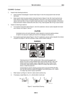
Invert injector on fixture. Using injector fuel line open end box wrench (Figure 2, Item 11), loosen injector nut
(Figure 2, Item 6) from injector.
7.
Lift injector nut (Figure 2, Item 6) straight up.
11
6
4
MAINT_277A
Figure 2.
Injector Nut Removal.
TM 9-2815-205-24
0084
0084-2
Back to Top


