TM-9-2815-205-24 - Page 553 of 856
ASSEMBLY - Continued
3.
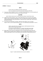
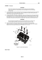
Install adapter (Figure 20, Item 46) into bore at outboard side of cylinder head; lower front hole on left head
and lower rear hole on right head. Apply sealing compound to adapter and drive flush to 0.03 inch
(0.76 mm) below surface.
4.
Install fuse plug (Figure 20, Item 47) into adapter (Figure 20, Item 46).
5.
Install three new expansion plugs (Figure 20, Item 45) at outboard side of cylinder head.
6.
Install four pipe plugs (Figure 20, Item 38) in fuel galleries on inboard side of cylinder head.
7.
Install pipe plug (Figure 20, Item 36) in oil gallery at each end of cylinder head.
NOTE
Model 5063-5392 uses one threaded plug (Figure 20, Item 39) at rear of left
cylinder head.
Models 5063-5393 and 5063-539L uses one threaded plug (Figure 20, Item 39) at
both ends of left cylinder head.
8.
If removed, install six threaded plugs (Figure 20, Item 39), except where noted, in cylinder head. One plug
located at each end and four plugs located in inboard side of cylinder head.
9.
If any exhaust manifold stud (Figure 20, Item 48) was removed, apply sealing compound to threads of stud
and install in outboard side of cylinder head. Torque stud to 25–40 lb-ft (34–54 N·m). Stud must protrude
1-7/16 – 1-1/2 inches (3.5–3.8 cm) from face of cylinder head.
10.
Install six fuel nipples (Figure 20, Item 9) and six new copper flat washers (Figure 20, Item 35) to fuel
galleries at top of cylinder head. Torque connectors to 20–28 lb-ft (27–38 N·m).
11.
Install new gasket (Figure 20, Item 44), cover (Figure 20, Item 43), two new lockwashers
(Figure 20, Item 42), and two bolts (Figure 20, Item 41) on rear of cylinder head.
9
47
48
37
37
35
39
39
39
36
41
42
43
44
45
46
36
37
38
39
40
OUTBOARD RIGHT
REAR VIEW
INBOARD LEFT
REAR VIEW
MAINT_267
Figure 20.
Cylinder Head Freeze Plug Assembly.
TM 9-2815-205-24
0083
0083-23
Back to Top


