TM-9-2815-205-24 - Page 558 of 856
ASSEMBLY - Continued
NOTE
If a new rocker arm is installed, also install a new push rod.
Push rod nut adjustment is performed during Engine Adjustment (WP 0078).
27.
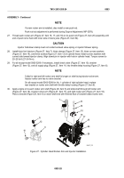
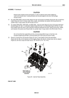
Thread each rocker arm (Figure 27, Item 16, 17, and 18) on its push rod (Figure 27, Item 20) assembly until
end of push rod is flush with inner side of clevis yoke (Figure 27, Item 94).
CAUTION
Injector hold-down clamp must not contact exhaust valve spring or injector follower spring.
28.
Install three fuel injectors (Figure 27, Item 7), three clamps (Figure 27, Item 15), three convex washers
(Figure 27, Item 14), and three screws (Figure 27, Item 13) in cylinder head. Install convex washers with
curved side toward injector clamp. Align dowel pin in injector with hole in cylinder head. Torque screws to
20–25 lb-ft (27–34 N·m).
29.
For all except model 5063-5299: if necessary, install check valve (Figure 27, Item 10), strainer
(Figure 27, Item 12), and oil supply plug (Figure 27, Item 11) into throttle delay housing (Figure 27, Item 6).
NOTE
Collar for right and left rocker arm shaft is longer on side facing injector rocker arm.
Injector rocker arm has no valve bracket.
On all except model 5063-5299 for No. 1 cylinder of right cylinder head, replace
rear bracket on rocker arm shaft with throttle delay housing (Figure 27, Item 6).
30.
Apply engine oil to each rocker arm shaft (Figure 28, Item 5) and slide shaft through left rocker arm
(Figure 27, Item 16), injector rocker arm (Figure 27, Item 17), and right rocker arm (Figure 27, Item 18).
Place a bracket (Figure 28, Item 4) on each shaft end with finished face of bracket toward rocker arm.
7
6
10
11
12
16
17
18
13
14
15
94
20
MAINT_274
Figure 27.
Cylinder Head Rocker Arm and Injector Installation.
TM 9-2815-205-24
0083
0083-28
Back to Top

