TM-9-2815-205-24 - Page 563 of 856
DISASSEMBLY - Continued
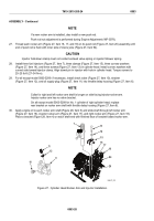
NOTE
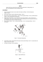
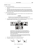
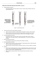
When injector has been in service for an extended period, spray tip assembly may
not be easily pushed from nut. In this case, support nut on a wood block and drive
tip out with spray tip driver (Figure 3, Item 25).
Do not dislodge spray tip and valve parts during injector nut removal.
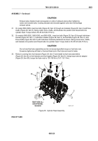
8.
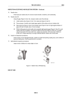
Remove spray tip (Figure 3, Item 5), needle valve (Figure 3, Item 12), spring cage (Figure 3, Item 13),
spring seat (Figure 3, Item 14), valve spring (Figure 3, Item 15), check valve cage (Figure 3, Item 16), and
check valve (Figure 3, Item 17).
9.
Remove spill deflector (Figure 3, Item 18).
10.
Lift bushing (Figure 3, Item 19) straight out of injector body (Figure 3, Item 23).
11.
Remove injector body (Figure 3, Item 23) from holding fixture (Figure 2, Item 4). Turn body upside down and
catch gear retainer (Figure 3, Item 20) and gear (Figure 3, Item 21) in hand as they fall from body.
12.
Remove injector control rack (Figure 3, Item 24) from body (Figure 3, Item 23).
13.
Remove preformed packing (Figure 3, Item 22) from body. Discard preformed packing.
6
5
12
13
14
15
16
17
18
19
20
21
22
23
24
25
6
5
MAINT_277
Figure 3.
Fuel Injector Exploded View.
END OF TASK
TM 9-2815-205-24
0084
0084-3
Back to Top


