TM-9-2815-205-24 - Page 559 of 856
ASSEMBLY - Continued
CAUTION
Exhaust valve bracket must rest squarely on ends of exhaust valves when tightening
rocker arm bracket bolts. Cocking exhaust valve bracket against valve stem will damage
exhaust valves.
31.
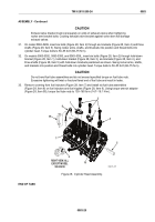
On model 5063-5299, insert six bolts (Figure 28, Item 2) through six brackets (Figure 28, Item 4) and three
shafts (Figure 28, Item 5). Swing rocker arms, shafts, and brackets into position and thread bolts into
cylinder head. Torque bolts to 50–55 lb-ft (68–75 N·m).
32.
On models 5063-5392, 5063-5393, and 5063-539L, insert six bolts (Figure 28, Item 2) through hold-down
bracket (Figure 28, Item 1), hold-down bracket (Figure 28, Item 3), six brackets (Figure 28, Item 4), and
three shafts (Figure 28, Item 5) with hold-down brackets positioned as shown. Swing rocker arms, shafts,
and brackets into position and thread bolts into cylinder head. Torque bolts to 50–55 lb-ft (68–75 N·m).
CAUTION
Do not bend fuel tube assemblies and do not exceed specified torque on fuel tube nuts.
Excessive tightening will twist or fracture flared end of fuel tube and result in leaks.
33.
Remove covering from fuel injectors (Figure 28, Item 7) and install six fuel tube assemblies
(Figure 28, Item 8) on fuel injectors and fuel nipples (Figure 28, Item 9). Using torque wrench adapter
(Figure 28, Item 95), torque fuel tube nuts to 130–160 lb-in (14.7–18.1 N·m).
8
95
9
2
4
1
3
16
5
6
RIGHT VIEW, ALL
EXCEPT MODEL
5063-5299
7
MAINT_275
Figure 28.
Cylinder Head Assembly.
END OF TASK
TM 9-2815-205-24
0083
0083-29
Back to Top

