TM-9-2815-205-24 - Page 700 of 856
DISASSEMBLY
1.
Secure piston and connecting rod assembly (Figure 2, Item 9) in a machinist vise with vise jaw caps.
2.
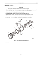
Using piston ring tool, remove fire ring (Figure 2, Item 12), two compression rings (Figure 2, Item 13), thick
oil control ring (Figure 2, Item 10), and two thin oil control rings (Figure 2, Item 14) from piston assembly
(Figure 2, Item 11). Discard rings.
3.
Remove two oil ring expanders (Figure 2, Item 15) from lower grooves in piston. Discard expanders.
4.
Secure piston and connecting rod assembly (Figure 2, Item 8) upside down in a machinist vise with vise
jaw caps.
5.
Loosen two bolts (Figure 3, Item 23) from connecting rod (Figure 3, Item 22) and piston pin
(Figure 3, Item 20). Remove assembly from machinist vise.
6.
Remove two bolts, two spacers (Figure 3, Item 24), and connecting rod. Discard bolts and spacers.
7.
Lay piston assembly (Figure 2, Item 11) horizontally on flat surface.
11
9
14
15
14
15
10
12
13
MAINT_372
Figure 2.
Piston Ring Disassembly.
TM 9-2815-205-24
0095
0095-4
Back to Top


