TM-9-2815-205-24 - Page 708 of 856
ASSEMBLY
1.
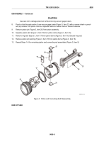
Piston and rod assembly procedures:
a.
Install pin bushing (Figure 9, Item 19) in piston dome (Figure 9, Item 16). Bushing must slide into
piston dome without force.
NOTE
Soak ring seal in engine oil for 15 minutes prior to installation on dome.
b.
Lubricate ring seal (Figure 9, Item 17) with engine oil and install in groove on piston dome
(Figure 9, Item 16).
c.
Align piston pin holes in skirt (Figure 9, Item 18) and dome (Figure 9, Item 16), then push skirt into
position on dome.
d.
Apply clean engine oil to piston pin (Figure 9, Item 20) and piston pin bushing (Figure 9, Item 19) and
install piston pin.
e.
Install spacers (Figure 9, Item 24) on piston pin bolts (Figure 9, Item 23). Apply small amount of Water
Displacing Compound, or equivalent, to bolt threads and bolt head contact surfaces.
f.
Install connecting rod (Figure 9, Item 22), two spacers (Figure 9, Item 24), and two bolts
(Figure 9, Item 23) on piston pin (Figure 9, Item 20). Tighten bolts finger tight.
g.
Clamp connecting rod (Figure 9, Item 22) in machinist vise with vise jaw caps and torque piston pin
bolts (Figure 9, Item 23) to 30–35 lb-ft (41–47 N·m). Do not exceed this torque.
CAUTION
Ensure vacuum gage testers do not buckle during installation and seat completely in
counterbore with spacing even around retainer to seal properly.
h.
Insert first vacuum gage tester (Figure 9, Item 21) in position. Place crowned end of piston pin installer
(Figure 9, Item 28) against retainer. Strike tool just hard enough to deflect retainer and to seat it evenly
in skirt (Figure 9, Item 18). Install second retainer in same manner.
16
17
23
24
28
18
19
21
21
20
22
MAINT_379
Figure 9.
Piston and Connecting Rod Assembly.
TM 9-2815-205-24
0095
0095-12
Back to Top


