TM-9-2815-205-24 - Page 717 of 856
INSTALLATION - Continued
NOTE
Connecting rod bolt must not turn in connecting rod when torquing nut.
8.
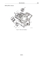
To check bearing to crankshaft journal clearance, place a plastic gage strip (Figure 15, Item 35) between
crankshaft journal (Figure 15, Item 5) and connecting rod cap (Figure 15, Item 7). Tighten connecting rod
nuts (Figure 15, Item 6) to 40–45 lb-ft (54–61 N·m). Remove connecting rod nuts and cap, and measure
width of plastic gage with measuring strip (Figure 15, Item 36). Maximum clearance with used parts is
0.006 inch (0.152 mm).
9.
Lubricate lower bearing shell (Figure 15, Item 8) with clean engine oil and install bearing cap
(Figure 15, Item 7) and bearing shell on connecting rod (Figure 15, Item 22) with identification numbers on
cap and rod adjacent to each other. Torque connecting rod bolt nuts (Figure 15, Item 6) to 40–45 lb-ft
(54–61 N·m).
37
8
6
35
22
7
7
36
8
33
34
5
MAINT_385
Figure 15.
Piston Connecting Rod Installation.
TM 9-2815-205-24
0095
0095-21
Back to Top


