TM-9-2815-205-24 - Page 718 of 856
INSTALLATION - Continued
NOTE
If necessary, pry connecting rods apart before measuring side clearance.
10.
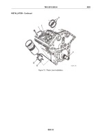
Using piston-liner thickness gage set, measure side clearance between each pair of connecting rods
(Figure 16, Item 22). Clearance must be 0.008–0.016 inch (0.20–0.41 mm).
11.
Repeat Steps 1–10 to install additional liners, pistons, and rod assemblies. Use cylinder liner hold-down
clamps (Figure 16, Item 2) to hold each liner in place.
12.
Remove all liner cylinder liner hold-down clamps (Figure 16, Item 2).
22
2
MAINT_386
Figure 16.
Connecting Rod Side Clearance and Piston Cylinder Liner Hold-Down Clamp.
END OF TASK
FOLLOW ON TASK
1.
Install cylinder head (WP 0073).
2.
Install oil pump inlet tubes (WP 0065).
3.
Install oil pan (WP 0063).
END OF TASK
END OF WORK PACKAGE
TM 9-2815-205-24
0095
0095-22
Back to Top


