TM-9-2815-205-24 - Page 711 of 856
ASSEMBLY - Continued
d.
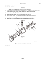
Using piston ring tool, install thick oil control ring (Figure 11, Item 10) in groove D (Figure 11, Item D)
(upper groove). Position gap in ring 180 degrees from gap in expander (Figure 11, Item 15). Press ring
against gap side of expander to prevent ends of expander from overlapping. Align ring with groove
and release tension on remover and replace.
NOTE
Install fire ring (Figure 11, Item 12) with dark side (with prestress mark) toward top
of dome.
e.
Using piston ring tool and starting from bottom, first install two compression rings (Figure 11, Item 13)
and then install fire ring (Figure 11, Item 12).
f.
Stagger ring gaps around piston a minimum of 90 degrees from each other.
12
18
14
15
15
14
10
D
C
EXPANDER ENDS
AWAY FROM TOP
OF DOME
BOTTOM OIL
CONTROL RINGS
(NOTE: EDGE
OF TOP RING
FACING UP)
TOP OIL
CONTROL
RING
TOP
13
MAINT_381
Figure 11.
Piston Ring Placement.
TM 9-2815-205-24
0095
0095-15
Back to Top


