TM-9-2815-205-34 - Page 452 of 596
TM 9-2815-205-34
3-65. FUEL INJECTOR ASSEMBLY REPAIR (Cont)
f. Testing
(1) Injector control rack freeness
(a)
(b)
(c)
(d)
(e)
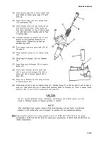
Place injector in injector tip and concentricity gage (34).
Hold rack (24) in NO FUEL position (rack extended all the way out).
Using handle (35), depress follower to bottom of its stroke.
Slowly release pressure on handle
(35) while moving rack (24) in and out
until follower reaches top of its travel.
Injector passes test if rack falls freely
when fully extended and released.
If rack binds, loosen injector nut, turn
tip, and then retighten nut. Loosen
and tighten nut several times if
necessary. If rack still binds, change
injector nut. Finally, if rack binds,
disassemble injector to eliminate
cause of misaligned parts or to
remove dirt.
(2) Spray tip concentricity
(a)
(b)
(c)
(d)
Place injector in injector tip and
concentricity gage (34).
Adjust dial indicator (36) to zero.
Rotate injector 360 degrees and note total runout as indicated on dial.
If total runout exceeds 0.008 inch, remove injector from gage. Loosen injector nut, center
spray tip, and torque nut. Check spray tip concentricity again. If, after several attempts,
spray tip cannot be positioned satisfactorily, replace injector nut.
(3) High pressure leak test
WARNING
•
Always hold injector so that fuel spray cannot penetrate skin. Fuel oil which
enters blood stream may cause serious infection.
•
Compressed air used for cleaning purposes will not exceed 30 PSI. Use only
with effective chip guarding and personal protective equipment (goggles/shield,
gloves, etc.)
(a) Thoroughly dry injector with compressed air.
(b) Place injector in diesel fuel tester (37).
3-324
Back to Top


