TM-9-2815-205-34 - Page 461 of 596
(5)
(6)
(7)
(8)
(9)
(10)
(11)
(12)
(13)
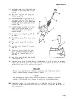
Install special washers (26) and shims
(16).
TM 9-2815-205-34
(27) in counterbore in inside face of gear (11) and gear
NOT E
Replace blower gears as a matched set.
Place flat in spline in left rotor (8) facing top of blower and flat ins line in right rotor (7) facing
left side of blower (forming the rotors into a "T” shape) as shown. hen place right gear (11) on
rotor (7) and left gear (16) on rotor (8) with flats in splines on gears in alignment with flats in
splines on rotor shafts.
Tap gears (11 and 16) lightly with a soft head hammer to seat them on shafts. Rotate gears
until timing marks (44) on face of gears match. Reposition gears if marks do not match.
Wedge a clean folded rag between blower rotors (7 and 8).
Install twelve-point bolt (22), bolt (24), and two 5/16-inch flat washers (45) in gears (11 and 16).
Turn bolts simultaneously and force gears on rotor shafts until tight against shoulders of rotor.
Remove bolt (22), bolt (24), and two flat washers (45).
Install two thrust washers (21) and two self-locking bolts (20) to front of blower rotors. Torque
bolts to 54-59 Ib-ft (73-80 N-m).
Install three spacers (19), thrust plate (18), and three self-locking bolts (17) on front end plate
(6). Torque bolts to 84-108 lb-in (10-12 N-m).
Using thickness gage set, check clearance between thrust plate (18) and thrust washers (21).
Clearance must be 0.0025 to 0.0050 inch.
3-333
Back to Top


